
ID : 10978
Auto Gain Tuning Procedure
The robot controller performs acceleration/deceleration operation of the auxiliary axes according to the default pattern preset in the controller.
Based on the motion of the auxiliary axes in that operation, the controller will estimate the inertia of payload and set the appropriate gain automatically.
To implement auto gain tuning, your optional mechanism to be connected to the auxiliary axis motor should satisfy the requirements given below. Otherwise, some errors may occur and the auto gain tuning process may be interrupted.
When executing auto gain tuning, keep off the motion range of the axis because the robot may move faster than in Manual mode.
- If the AutoPositionClear is enabled, disable it.
- The auto gain tuning function is not available while [Enable Servo amplifier custom setting] is being enabled.
Auto Gain Tuning Procedure
- The inertia of payload should be within the motor specifications and should not deviate greatly.
- The rigidity of the torque transmission mechanism (including motor and coupling) to be connected to the auxiliary axis motor should be high.
- The backlash in the torque transmission mechanism should be minimized.
- Rotating the motor in the + and − directions alternately two times respectively should result in no problem.
Auto Gain Tuning Procedure
This operation is available only when the currently logged-in account is granted user permission for "Maintenance".
1
Turn the motor power on.
If the robot is in Auto mode, switch it to Manual mode.
2
Get out of the motion range so that there will be no problem even if the motor rotates in the + and − directions alternately two times respectively.
3
Press Top Screen - [F2 Arm] - [F12 Maintenance] - [F10 Joint Settings] to display the [Joint Settings] window.
4
Press [F7 Auto Gain Tuning].
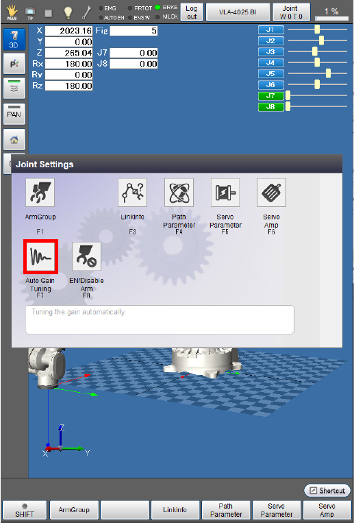
The [Auto Gain Tuning] window appears.
5
Choose the joint number that should undergo auto gain tuning.
The following example is the display when the 7th axis is selected.

6
Select the motor rotation direction.
The following example is the display when the [Minus(-)] direction is selected.
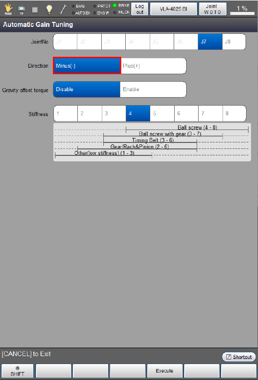
7
Select whether the [gravity offset torque] should be enabled or disabled.
The following example is the display when the [gravity offset torque] is enabled.

If an unbalanced load applies to the motor, be sure to enable the [gravity offset torque].
If you enable the [gravity offset torque] for auto gain tuning, the controller will automatically calculate the torque offset included in servo configuration parameters. On the [Joint Settings] window, press [F5 Servo Parameter] to call up the [Servo parameter] window and then press [OK] to save the calculated torque offset value.
8
Select the mechanical stiffness, referring to the stiffness reference values listed below.
The following example is the display when "4" is selected.
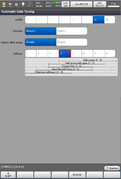
| Types of Torque Transmission Mechanisms | Mechanical stiffness |
|---|---|
| Ball screw | 4 to 8 |
| Ball screw with gear | 3 to 7 |
| TimingBelt | 3 to 6 |
| Gear/Rack & Pinion | 2 to 6 |
| Other low stiffness | 1 to 3 |
9
Press [F4 Execute].
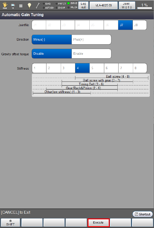
The following system message appears.
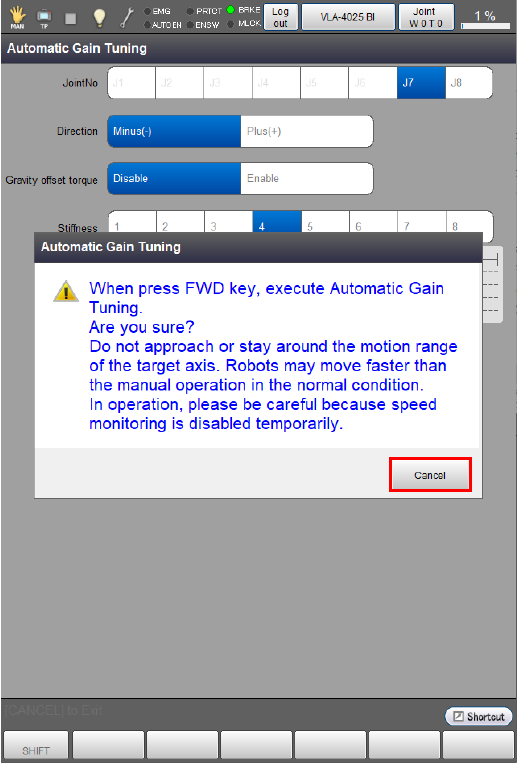
Pressing [FWD] on Smart TP while holding down the enabling switch will start auto gain tuning.
Hold down both the [FWD] button and the enabling switch during auto gain tuning. Releasing either of them will interrupt auto gain tuning.
10
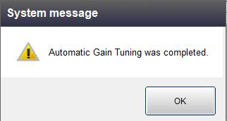
The controller calculates the gain after the axis performs two set of the two-time rotations in each ± direction. This completes auto gain tuning.
After the auto gain tuning operation is complete, the following message appears. Restart the RC9 robot controller.
Setting a higher mechanical rigidity can cause an abnormal noise or vibration during auto gain tuning.
In this case, set a lower mechanical rigidity and restart auto gain tuning.
ID : 10978