
ID : 4822
Electrical Wiring and Air Piping of the Robot Unit
Make electrical wiring and air piping of the hand or tool to be attached to the arm end, referring to the example given below.
Use robot instrumentation cables (manufactured by Daikyo Denshi) or equivalent for electrical wiring.
Supply dry air filtered through an air filter (Recommended filtration rating: 5 μm or below).
Before piping, blow the air tube out with dry air to clean out the inside (flushing); otherwise, any chips, cutting oil, dust or dirt remaining in the air tube may result in a damaged valve.
Do not pass wires or pipes other than those provided by DENSO through the cable bear of the 1st axis. Doing so may break or damage them.
Air Piping and Signal Wiring
The XR series robot is equipped with 10 signal lines. Also, manifold valve with 4 systems(φ4×8)is available as option. Supply dry air through the air pipe for valve (φ8×1) to use manifold valve.
Signal Wiring, Air Piping and Connectors of the Robot Unit
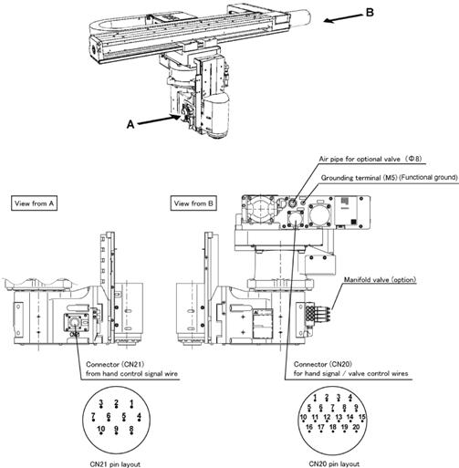
Pins #1 to #10 on CN21 and those on CN20 are connected with each other. The allowable current per line is 1A.
Use the attached connector sets for CN20 and CN21.
| Connector set part No. | Part No. | Model and part name | Appearance |
|---|---|---|---|
| 410889-003* | 410877-017* (for CN20) |
SRCN6A25-24S (round type connector) (Japan Aviation Electronics Industry Ltd) |  |
| 410877-018* (for CN21) |
JMLP1610M (L type plug connector) DDK Electronics, Inc. |  |
Connectors and Pin Assignment for Optional Valve
- CN20 Pin Assignment (for optional valve)
| CN20 pin No. | Used for: |
|---|---|
| 12 | +24V (*1), 0V (*2) |
| 13 | Solenoid 1A (solenoid valve 1) |
| 14 | Solenoid 1B (solenoid valve 1) |
| 15 | Solenoid 2A (solenoid valve 2) |
| 16 | Solenoid 2B (solenoid valve 2) |
| 17 | Solenoid 3A (solenoid valve 3) |
| 18 | Solenoid 3B (solenoid valve 3) |
| 19 | Solenoid 4A (solenoid valve 4) |
| 20 | Solenoid 4B (solenoid valve 4) |
*1 : NPN (source IN, sink OUT)
*2 : PNP (sink IN, source OUT)
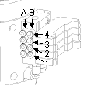
- Manifold Valve (option.)
Valve Symbols and Air Intake and Exhaust States.
| Air piping joint | Valve signal | |||
|---|---|---|---|---|
| Air intake | Exhaust | Solenoid valve | Solenoid | |
| A | B | |||
| 1A | 1B | 1 | ON | OFF |
| 1B | 1A | 1 | OFF | ON |
| 2A | 2B | 2 | ON | OFF |
| 2B | 2A | 2 | OFF | ON |
| 3A | 3B | 3 | ON | OFF |
| 3B | 3A | 3 | OFF | ON |
| 4A | 4B | 4 | ON | OFF |
| 4B | 4A | 4 | OFF | ON |
(1A and 1B are piping joint symbols.)
ID : 4822