
ID : 5504
Storing of the Controller
This section describes the process to store a controller in the controller protective box and to connect wires.
Before operation, make sure that there is no power supply from the facilities.
The following uses RC8 standard specification controller as an example.
Recommended torque : M3:0.6N・m, M4:1.5N・m, M5:3N・m
1
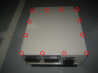
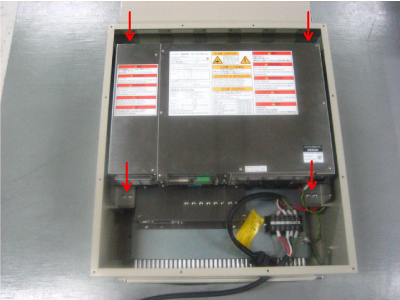
To remove the top panel, unscrew 12 of M4 screws on the top surface.
2
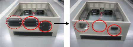
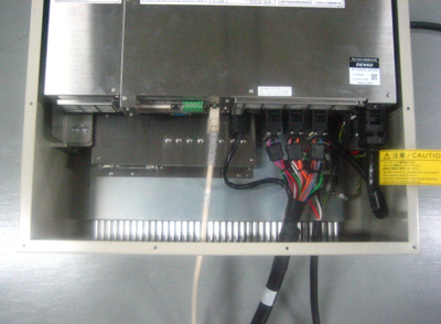
Remove two cable multi-outlet plates, marked by red circles (solid line) in the image below.
Remove six M5 screws for one cable multi-outlet plate.
To use 13 cables or more, remove the cable multi-outlet plate marked by a red circle (broken line) in the image below, as well.
3
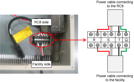
Remove the terminal board cover. Lay prepared power cable with M4 screws as shown below.
For the preparation of cables, see "Preparation of the power cable".
Once the power cable is laid, put the terminal board cover back in place.
4
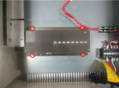
To use an encoder hub (option part), tighten the encoder hub with four of M4 screws marked by red circles in the image below.
5
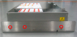
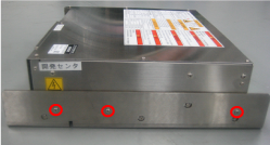
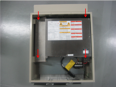
Attach the left bracket (small) and the right bracket (mounted on the controller protective box) to the left side and right side of the RC8, respectively. Tighten the brackets with M4 screws, marked by six of red circles on the image below.
| Left side of the RC8 | Right side of the RC8 |
|---|---|
 |
 |
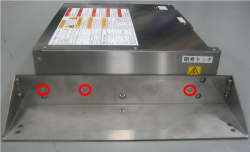
For the safety I/O less specification, attach the left bracket (large) to the left side of the RC8 as shown below.
| Left side of the RC8 |
|---|
 |
6
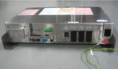
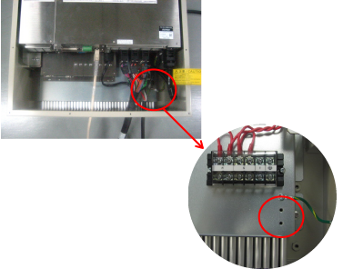
Connect the FG harness to the earthing point, marked by red circles (solid line) in the image below.
The image below shows the standard specification controller.
7
Tighten eight of mounting holes on the bracket with M5 screws.
The image below shows the safety I/O less specification controller.
8
Pass cables through the cable multi-outlet plates which was removed in the STEP2. Attach the plates to the RC8.
For information on how to attach the cable multi-outlet plates, see "Clamping the Cables".
9
Remove two of M4 screws close to the terminal board. Tighten the FG harness which was mounted in the STEP5 and the FG harness of the motor & encoder cable, by each screws, respectively.
Do not tighten two harnesses together.
10
Put the top plate back in place with 12 of M4 screws which was removed in the STEP1.
ID : 5504