ID : 5505
Clamp the Cables
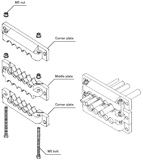
This section describes the process to clamp cables with the cable multi-outlet plate.

1
Install rubber packings in the ditches of the corner plate and the middle plate.
- Rubber Packing Set
| Model | Application cable dia | Application |
|---|---|---|
| EMSP0 | - | To be used as a blind cover |
| EMSP4 | φ4-φ6 | Communication cable |
| EMSP6 | φ6-φ8 | Pendant cable, Hand I/O cable |
| EMSP8 | φ8-φ10 | Mini I/O cable |
| EMSP10 | φ10-φ12 | Extended parallel I/O cable |
- Rubber Packing Set for Extended-Joint Cables
| Model | Application cable dia | Application |
|---|---|---|
| EMSP8 | φ8-φ10 | Extended-joint encoder cable |
| EMSP12 | φ12-φ14 | Extended-joint motor cable |
Note the following points when installing the EMS packings on the plates.
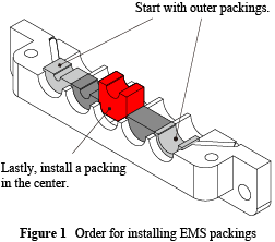
- Install the EMS packings in the ditches in order starting from both ends of the ditches to the center. (Figure 1)
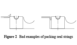
- Ensure that the ends of the packing seal strings mounted on the plates are neither lifted up by nor caught in the installed EMS packings. (Figure 2)


2
Pass the M5 bolts through the hex holes so that the head of bolts go under the hole.
3
Pass the cables through the holes between the corner plate and the middle plate. Adjust both plates to the vertical direction.
4
Attach the M5 nuts to the M5 bolts.
5
Tighten the corner plate and the middle plate with a spanner until no space remains between the plates.
6
Pass the cables through the holes between the middle plate and the corner plate. Adjust both plates to the vertical direction.
7
Attach M5 nuts to the M5 bolts.
8
Tighten the middle plate and the corner plates with a spanner until no space remains between the plates.
9
Pass the cables through the rectangular openings of the controller protective box. Tighten them from the front side with the M6 screws.
ID : 5505

