
ID : 4018
Connecting Emergency Stop Box and I/O
This section describes the connection procedures in the following order.
1. Connecting Emergency Stop Box
1
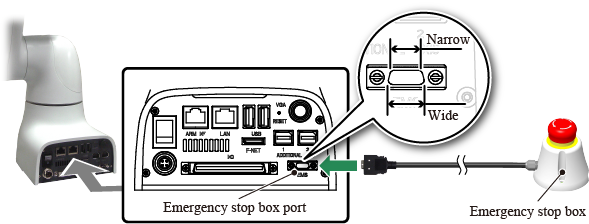
If fixing the emergency stop box, fix with screws. If you have not punched screw holes for fixing, punch them by referring to "Emergency Stop Box"and then fix the box with the screws.

2
Connect the emergency stop box to the emergency stop box port on COBOTTA. The port shape indicates a specific insertion direction. It is narrow at the top and wide at the bottom (Refer to the figure below). Plug the connector in the correct direction.
2. Connecting I/O
The I/O connection method varies depending on the situation as follows:
When not connecting an external device
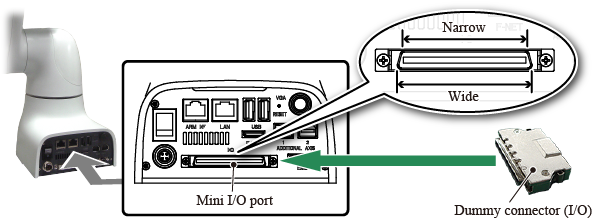
1
When you do not connect an external device, plug a dummy connector (I/O). Connect the dummy connector (I/O) to the Mini I/O port on COBOTTA. The port shape indicates a specific insertion direction. It is narrow at the top and wide at the bottom (Refer to the figure below). Plug the connector in the correct direction.
When connecting an external device
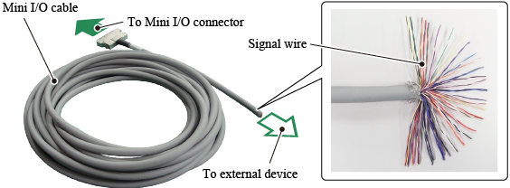
1
When you connect an external device, plug a Mini I/O cable. Connect the Mini I/O cable signal line to the external device.
Turn off the external device before connecting the Mini I/O cable to the external device.
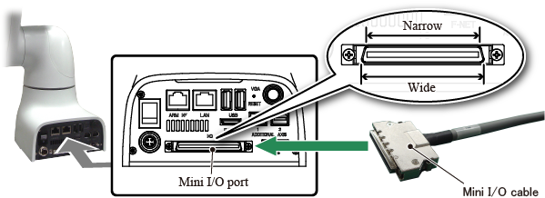
2
Connect the Mini I/O cable to the Mini I/O port on COBOTTA. The port shape indicates a specific insertion direction. It is narrow at the top and wide at the bottom (Refer to the figure below). Plug the connector in the correct direction.
ID : 4018