
ID : 7261
I/O Allocation
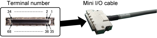
The following describes functions (signal names) that are allocated to terminals on a Mini I/O connector.
Each terminal of Mini I/O connector is given a number (terminal number).
The following table shows the correspondence between a terminal number and a signal name. As the following table shows, the allocation of words to the Input signal and output signal (I/O) are called "I/O allocation".
For about colors, marks of signal names, port numbers, refer to the descriptions written in the next of the table.
Also, in OSS version, some signals are restricted. For about restricted signals, refer to the descriptions in the table below.
Terminal number (Line color) |
Name of signal | Terminal number (Line color) |
Name of signal |
|---|---|---|---|
1 (black) |
Reserved | 35 (pink) |
Reserved |
2 (brown) |
 External emergency stop input signal 1b-1 External emergency stop input signal 1b-1 |
36 (pink) |
External emergency stop input signal 1b-2 |
3 (red) |
External emergency stop input signal 2b-1 |
37 (pink) |
External emergency stop input signal 2b-2 |
4 (orange) |
Protective stop input 1-1 |
38 (pink) |
Protective stop input 1-2 |
5 (yellow) |
Protective stop input 2-1 |
39 (pink) |
Protective stop input 2-2 |
6 (black) |
STO monitor output 1 |
40 (white) |
STO monitor output 2 |
7 (brown) |
Reserved | 41 (white) |
Reserved |
8 (red) |
42 (white) |
||
9 (orange) |
43 (white) |
||
10 (yellow) |
44 (white) |
||
11 (green) |
 Step stop (input) Step stop (input) |
45 (white) |
CPU normal (output) |
| Port number : 0 | Port number : 16 | ||
12 (blue) |
Strobe signal (input) |
46 (white) |
Robot running (output) |
| Port number : 1 | Port number : 17 | ||
13 (purple) |
Data area bit 0 (input) |
47 (white) |
Robot error (output) |
| Port number : 2 | Port number : 18 | ||
14 (gray) |
Data area bit 1 (input) |
48 (white) |
Robot initialized (output) |
| Port number : 3 | Port number : 19 | ||
15 (pink) |
Data area bit 2 (input) |
49 (white) |
 User output User output |
| Port number : 4 | Port number : 20 | ||
16 (black) |
Command area bit 0 (input) |
50 (gray) |
Operation preparation completed (output) |
| Port number : 5 | Port number : 21 | ||
17 (black) |
Command area bit 1 (input) |
51 (purple) |
Motion preparation completed (output) |
| Port number : 6 | Port number : 22 | ||
18 (brown) |
Command area bit 2 (input) |
52 (purple) |
Command processing completed (output) |
| Port number : 7 | Port number : 23 | ||
19 (red) |
User input |
53 (purple) |
User output/Continue start permission (output) |
| Port number : 8 | Port number : 24 | ||
20 (orange) |
User input |
54 (purple) |
User output |
| Port number : 9 | Port number : 25 | ||
21 (yellow) |
User input |
55 (purple) |
User output |
| Port number : 10 | Port number : 26 | ||
22 (green) |
User input |
56 (purple) |
User output |
| Port number : 11 | Port number : 27 | ||
23 (blue) |
User input |
57 (purple) |
User output |
| Port number : 12 | Port number : 28 | ||
24 (gray) |
User input |
58 (purple) |
User output |
| Port number : 13 | Port number : 29 | ||
25 (pink) |
User input |
59 (purple) |
User output |
| Port number : 14 | Port number : 30 | ||
26 (brown) |
User input |
60 (gray) |
User output |
| Port number : 15 | Port number : 31 | ||
27 (red) |
Reserved | 61 (gray) |
Reserved |
28 (orange) |
Emergency stop box status output 1b-1 |
62 (gray) |
Emergency stop box status output 1b-2 |
29 (yellow) |
Emergency stop box status output 2b-1 |
63 (gray) |
Emergency stop box status output 2b-2 |
30 (green) |
Reserved | 64 (gray) |
Reserved |
31 (blue) |
65 (gray) |
||
32 (pink) |
|
66 (gray) |
|
33 (black) |
67 (blue) |
||
34 (brown) |
68 (blue) |
Treat unused terminals so that they are not contact with any conductive objects, such as other terminals or metal part. Doing so may damage or break equipment.
- A line color shows the color of signal line of Mini I/O cable (option). For more details, refer to "Wiring of Mini I/O Cable".
-
A mark on each signal name shows the category of signal. The following shows the correspondence between mark and category.
: A safety signal. A signal that stops COBOTTA or outputs the stop-state is classified in this category. : A system function signal. A signal that starts/stops a COBOTTA's robot program from an external device is classified in this category. : A user signal. A signal where users can use freely in a COBOTTA's robot program is classified in this category. - A signal described with a port number can be used in a robot program. To read from and write to a signal in a robot program, specify this port number.
- Mini I/Os are classified into two types by signal circuits; NPN and PNP. I/O allocations for NPN and PNP are the same. (Same as above table)
- For more details of each signal, refer to "System I/O Signals".
-
For OSS version, the following restrictions are applied.
System function signals work the “terminal number 45 : CPU normal(output)” only. Other signals are not available.
All of user signals are not available.
ID : 7261