
ID : 2457
CALSET
What is a CALSET Position?
Calibrating the relationship between position-related information recognized by the robot controller and the actual position of the robot unit is called CALSET.
CALSET uses a previously determined axis position where an axis can be secured. It creates calibration data (CALSET data) that matches the actual axis position (CALSET position) with the encoder value. The angle of the CALSET position is saved in the robot controller as a RANG value.
The CALSET data is different on each robot.
CALSET must be performed when the motor is replaced or when the encoder backup battery goes dead and the position-related data retained in the encoder is lost as a result.
CALSET data should be managed by the customer.
Back up the CALSET data periodically, referring to "Backing up Projects".
Factory Defaults of CALSET Position
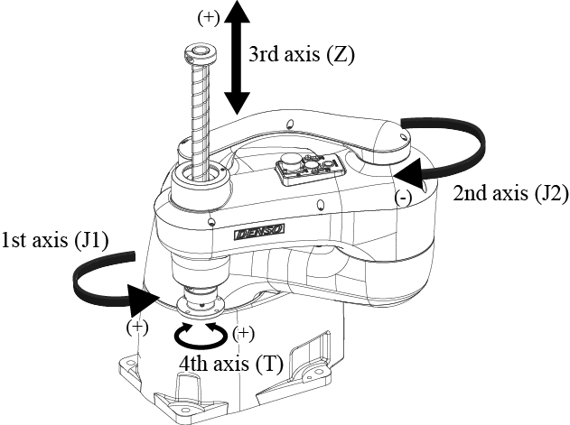
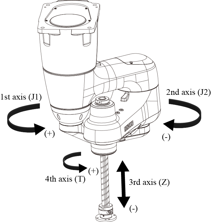
Each axis has a mechanical end in each of the positive and negative directions. The CALSET to be carried out before shipment uses mechanical ends shown below as CALSET positions.
| Location | 1st axis | Turning end in the positive direction (counterclockwise end when viewed from the top) |
|---|---|---|
| 2nd axis | Turning end in the negative direction (clockwise end when viewed from the top) | |
| 3rd axis |
|
|
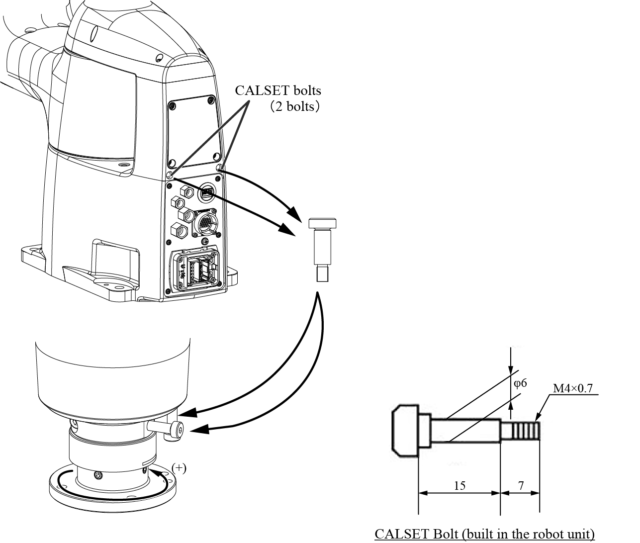
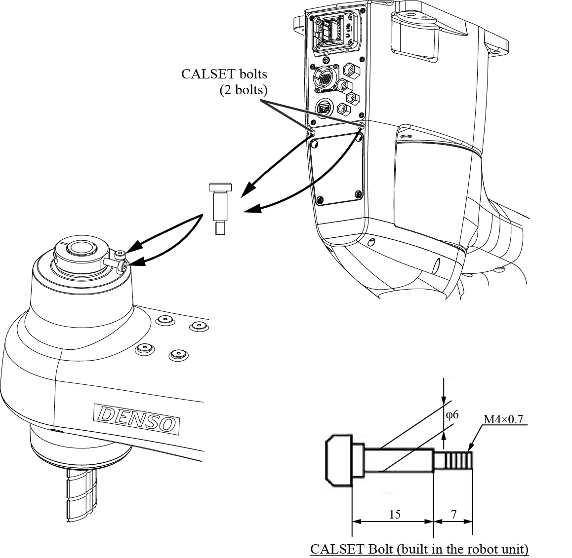
| 4th axis | Turning end in the positive direction (counterclockwise end when viewed from the top) To CALSET the 4th axis, two CALSET bolts mounted on the robot unit are required. After completion of CALSET, put the CALSET bolts back into place. (See the figure below.) |
|
| External appearance | Floor-mount |
|
Mounting CALSET Bolts on the 4th Axis
To mount those bolts for the bellows type, dust- & splash-proof type, cleanroom type, H1 grease type, remove the bottom bellows. |
||
| Overhead-mount |
To mount those bolts for the bellows type, dust- & splash-proof type, cleanroom type, H1 grease type, remove the upper bellows. |
|
Mounting CALSET Bolts on the 4th Axis
|
Preparation for CALSET
Press each of the axes against the associated mechanical ends by hand to get the actual positions.
CALSET requires some space for bringing each axis into contact with the mechanical end.
- When CALSETing, move the axis to be CALSET in the vicinity of the mechanical end, release the brake, and bring the axis into contact with the mechanical end.
- After CALSET, confirm in the manual mode that each axis stops at the software motion limit before coming into contact with the mechanical end.
- In automatic operation, start to run the robot at low speed. Ensuring safety, gradually increase the speed. It makes adjustment easy.
- Position-related data in some programs made before CALSET may vary somewhat after CALSET.
CALSET Procedure
1
Release the brake of an axis to be CALSET and move the axis to the CALSET position.
2
Use the teach pendant to select CALSET.
For detail operation, refer to "Displaying CALSET Operation Menu".
You must perform CALSET of the 3rd-axis before that of the 4th-axis. In doing so, CALSET of the 3rd-axis will fail. Follow the order of the CALSET at any time.
ID : 2457