ID : 3328
MC8 Series-Controlled Robot × 2 Selective Joint Only
This page describes the system configuration and the details in the following sections.
System Configuration Layout
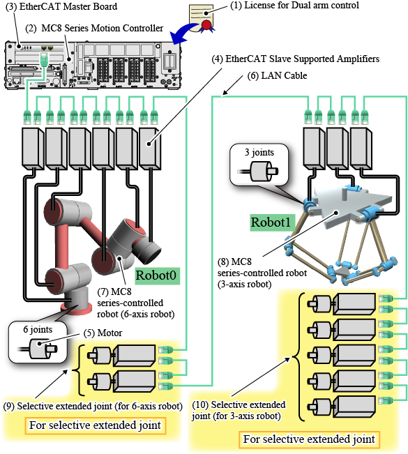
The following figure illustrates the overall system configuration.
(In the following example, a 6-axis robot and a 3-axis robot are controlled as MC8 series-supported robots.)

Components
| Component | Description | ||||||||||
|---|---|---|---|---|---|---|---|---|---|---|---|
(1) License for Dual arm control |
This system requires a license for the dual arm control. For details, refer to "License". |
||||||||||
(2) MC8 Series Motion Controller |
Controls two MC8 series-controlled robots. In the above-mentioned system, either an MC8 or an MC8A are available. The system configuration above is also applied to the MC8 series motion controller UL-listed model. For details about external view and specification, refer to "MC8 SERIES (MOTION CONTROLLER) MANUAL". |
||||||||||
(3) EtherCAT Master Board |
Enables the EtherCAT communication with selective joints. To use this board, you need to prepare a software license. There are four types of software license-board combinations as follows.
|
||||||||||
(4) EtherCAT Slave Supported Amplifiers |
Available amplifier are predetermined. In the "SELECTIVE EXTENDED JOINT (ETHERCAT) MANUAL", in the "Hardware Connection Structure", refer to "EtherCAT Slave Supported Amplifier". |
||||||||||
(5) Motor |
A motor for a selective joint. Select a motor that can run with the EtherCAT Slave-supported amplifier to use. | ||||||||||
(6) LAN Cable |
EtherCAT communication cable. Use a twisted pair LAN cable of category 5 or higher. Either a straight- or a cross-LAN cable can be used.
|
||||||||||
(7) MC8 series-controlled robot (6-axis robot) |
Any robots designed and/or created by users. Whether the target robot name is assigned as Robot0 or Robot1 is determined by the EtherCAT Slave-supported amplifier being connected to the target robot. An EtherCAT Slave-supported amplifier which connects to the EtherCAT master board first will be assigned to the 1st-axis of Robot0. The next amplifier will be assigned to the 2nd-axis of Robot0. For further information, refer to "Selective Joint Assignment to Each Robot". To use the kinematics configuration, you need to purchase a paid software license.
For details about the kinematics configuration, refer to "Kinematics Configuration" in the "MC8 SERIES (MOTION CONTROLLER) MANUAL". |
||||||||||
(8) MC8 series-controlled robot (3-axis robot) |
|||||||||||
(9) Selective extended joint (for 6-axis robot) |
To use an extended joint, connect the extended joint as the figure above. The following shows the maximum and minimum numbers of joints per robot for this use.
Do not connect any joints if you do not use them. |
||||||||||
(10) Selective extended joint (for 3-axis robot) |
Attention
-
Before connecting each device, read the following linked pages carefully for safe operation.
Link - "Installation" in the "RC8 SERIES ROBOT CONTROLLER MANUAL"
- "Hardware Connection Structure" in the "SELECTIVE EXTENDED JOINT (ETHERCAT) MANUAL"
-
Before the system design and/or operation, read the following linked pages carefully for your safety.
Link
ID : 3328

