
ID : 4635
Reference Drawing for Stay 1
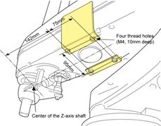
Stay 1 For HM-4*60* (-W) and HM/HMS-4*70* (-W)
Mounting |
HM-4*60* (-W) HM/HMS-4*70* (-W)
|
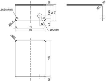
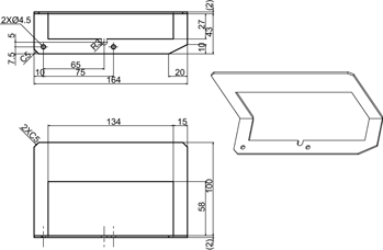
Drawing of Stay 1 |
HM-4*60* (-W) HM/HMS-4*70* (-W)
No burr permitted Recommended material: SPCC (t2.0) Surface treatment: Galvanizing Unit: mm |
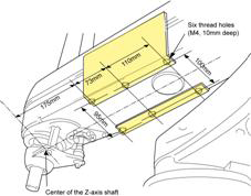
Stay 1 For HM/HMS-4*85* (-W) and HM-4*A0* (-W)
| Mounting | HM/HMS-4*85* (-W) HM-4*A0* (-W)
|
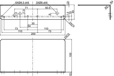
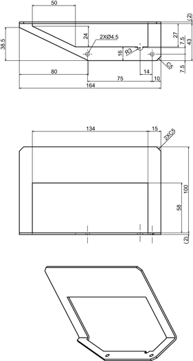
Drawing of Stay 1 |
HM/HMS-4*85* (-W) HM-4*A0* (-W)
No burr permitted Recommended material: SPCC (t2.0) Surface treatment: Galvanizing Unit: mm |
Stay 1 For HM-4*60*-UL
For the UL-listed robot unit with 600 mm stroke (HM-4*60*-UL), prepare stays L and R exclusively designed for the left and right sides, following the drawings shown below. This is because mounting the stay shown in above on this robot unit may cause the first arm cover to interfere with the stay when the robot arm moves near the factory default software motion limit position.
| Mounting | 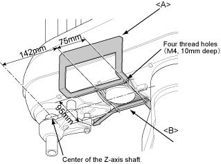 |
|---|---|
| Drawing of Stay 1 | <A>
No burr permitted Recommended material: SPCC (t2.0) Surface treatment: Galvanizing Unit: mm |
<B>
No burr permitted Recommended material: SPCC (t2.0) Surface treatment: Galvanizing Unit: mm |
ID : 4635