
ID : 5450
Precautions about CALSET for the VS-6556/6577 Series
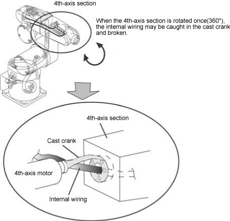
Robots in the VS-6556/6577 series have no mechanical stop on the 4th-axis.
If the 4th-axis CALSET position is wrongly set by one rotation (360°) while CALSET is being carried out, the internal wiring may be caught in the crank and broken. To carry out CALSET with a robot with no 4th-axis mechanical stop, check the normal 4th-axis position first as described below.
|
Note that turning the 4th-axis section by more than 360° may break the internal wiring
Checking of 4th-axis Position before Carrying Out CALSET
- Manually move the 4th-axis section until the hand control signal connector comes to the upper side.
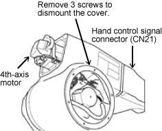
- Dismount the cover from the second arm so that the internal
wiring can be checked. The cover to
dismount for each model is shown below:
VS-6577 VS-6556 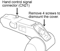
- Check that the 4th-axis section is at a designated position.
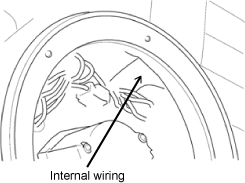
(The hand control signal connector (CN21) of the second arm comes to the upper side and the internal wiring is not caught in the crank at this time.)Checking the 4th-axis position for VS-6577 The internal wiring is visible in the normal condition.
(It is not visible if caught in the crank.)
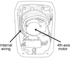
Checking the 4th-axis position for VS-6556 The internal wiring is visible in the normal condition as below.
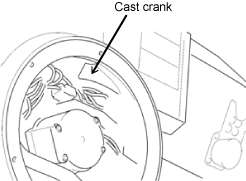
When the 4th-axis section is rotated from where it is as shown on the left, the internal wiring is caught in the crank and becomes invisible in the left figure. (The figure below shows the crank at around 250°.)
- When the 4th-axis section is not at the normal position, manually move it to a designated position. Preparation before carrying out CALSET is finished now.
If the step is omitted, the 4th-axis CALSET position may be mistaken by one rotation (360°). The internal wiring may be caught in the crank and broken in such a case.
ID : 5450