
ID : 10192
Check the Load Applied to the Robot End
This section describes the following items.
- Load Allowance
- How to Check if the Load is within the Allowable Range based on the Mass and the Center of Gravity Position
- Moment of Inertia Calculation
Load Allowance
Design or select a robot tool to meet the requirements described below. (refer to "Specifications of Robot Unit")
- Maximum payload
- Allowable moment of inertia (kgm²)
- Allowable moment (Nm)
In calculation for tool design, take into account not only a tool but also all loads to be applied to the flange, such as tool fixing parts, workpieces, wiring and piping.
Also, a tool (including workpiece) should not vibrate.
If these requirements are not met, the clamped sections of the robot unit may become loose, rattle or get out of position. In the worst case, the mechanical parts of the robot and the controller may become damaged.
A continuous fine, low speed motion may cause an overload error.
How to Check if the Load is within the Allowable Range based on the Mass and the Center of Gravity Position
When calculating the moment of inertia and the moment applied on the robot end, the shape of object that charges load on the flange (hereafter, total load on the flange), such as a tool and workpiece, needs to be used in the calculation formula.
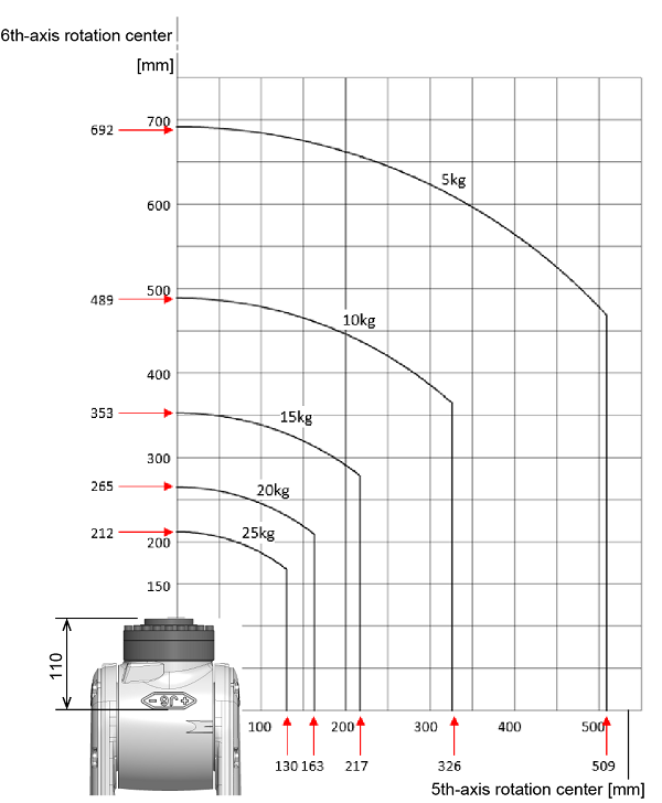
However, if the position of the mass and the center of gravity of the total load on the flange have been known, you can use the following graph to check if each value is within the allowable range.
The following graph shows the allowable relationship among the center of gravity of the total load on the flange, the distance from the 6th-axis rotation center, and the distance from the 5th-axis rotation center, for respective mass.
For example, suppose that the mass of the total load on the flange is 10kg. In this case, if the center of gravity of the total load on the flange is within the "10kg" line in the graph, the moment of inertia and the moment are within the allowable range.
However, the values of mass of the total load on the flange described the following graph are relatively small ones. If the mass of the total load on the flange is larger than this graph shows, figure out each load from "Moment of inertia calculation" to check if these values are within the allowable range.
Moment of Inertia Calculation
To figure out the moment of inertia that the total load on the flange applies around the 4th-, 5th-, and 6th-axis, refer to the following calculation formula.
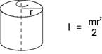
1. Cylinder(1) (Axis of rotation = Center axis)
|
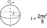
4. Sphere (Axis of rotation = Center axis)
|
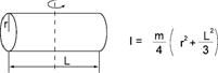
2. Cylinder(2) (The axis of rotation passes through the center of gravity.)
|
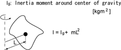
5. Center of gravity not on the axis of rotation
|
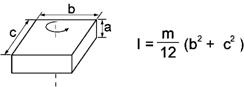
3. Rectangular parallelepiped (The axis of rotation passes through the center of gravity.)
|
I : Moment of inertia [kgm2] m : Mass [kg] r : Radius [m] a, b, c, L : Length [m] |
Calculation Example
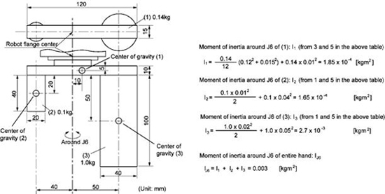
When calculating the moment of inertia of a complicated shape, divide it into simple parts as much as possible for easier calculations.
As shown in the figure below, divide the end-effector into three parts (1), (2), (3).
Moment of Inertia Around J6
 |
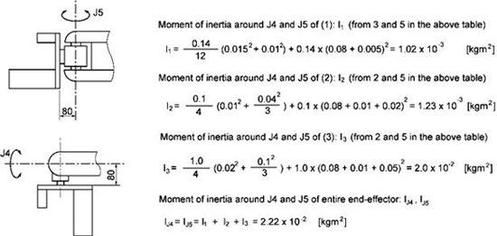
Moment of Inertia Around J4 and J5
For the end-effector shown below, the moment of inertia around J4 and J5 can be calculated according to the same formula.
 |
ID : 10192