
ID : 10193
Wiring and Piping to a Tool in Signal Lines & Air Piping Specification
This section describes the following items.
- Components to be Connected
- Position and Specification of Each Connector
- Precautions on Wiring·Piping
Components to be Connected
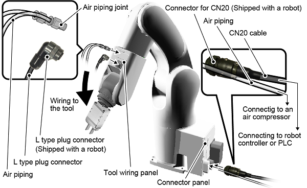
In the Signal line & Air Piping specification, as the following figure shows, signal lines and air pipes are connected from the tool wiring panel to the tool. Signal lines and air pipes, which are connecting to the connector panel, are directly connected to the tool wiring panel, passing through the inside of the robot body. Therefore, you do not need to lay wires and pipes between the tool wiring panel and the connector panel.
Among components illustrated above, the following table shows components to be prepared by customers.
| Customer prepared components | Components accompanied by the robot |
|---|---|
|
|
For information about the correspondence between connectors on the tool wiring panel and the ones on the connector panel, specifications of each connector, refer to "Position and Specification of Each Connector".
Position and Specification of Each Connector
This section describes the following information.
- Position and Specification of Each Connector on Tool wiring panel 1
- Position and Specification of Each Connector on Tool wiring panel 2
- Position and Specification of Each Connector on Connector Panel
- Pin Assignment on Each Connector
The connectors to use may differ depending on the option being used. For details about connectors to use, refer to "Equipment for Tool".
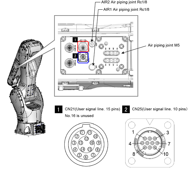
Position and Specification of Each Connector on Tool wiring panel 1
| Connector / specifications | Description |
|---|---|
Valve output
|
Connect to the port of the solenoid valve inside the robot (robot built-in solenoid valve). Air to the robot built-in solenoid valve is supplied through the AIR1 on the connector panel. For specification about the robot built-in solenoid valve, refer to this link. |
AIR1
|
Directly connected to AIR1 on the connector panel. To connect air piping. This connector is not available if the solenoid valve option is used. |
AIR2
|
Directly connected to AIR2 on the connector panel. To connect air piping. This connector is not available if the solenoid valve option for the clean room type is used. |
CN21Connector specifications on the cable side
|
Directly connected to CN20 on the connector panel. To connect signal lines to the tool. A connector on the cable side connecting to this connector is shipped with a robot unit. However, the connector plug is not connected to the cable. Please connect the cable to the connector plug on your own. |
CN25Connector specifications on the cable side
|
Directly connected to CN24 on the connector panel. To connect signal lines to the tool. A connector on the cable side (L type plug connector) connecting to this connector is shipped with a robot unit. However, the L type plug connector is not connected to the cable. Please connect the cable to the L type plug connector on your own. For information about how to connect the cable to the L type plug connector, refer to this link. |
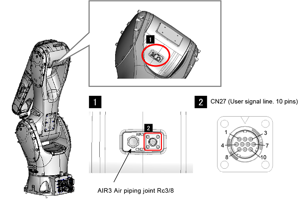
Position and Specification of Each Connector on Tool wiring panel 2
| Connector / specifications | Description |
|---|---|
AIR3
|
Directly connected to AIR3 on the connector panel. To connect air piping. |
CN27Specifications of connectors on the cable side(L type plug connector)
|
Directly connected to CN26 on the connector panel. To connect signal lines to the tool. A connector on the cable side (L type plug connector) connecting to this connector is shipped with a robot unit. However, the L type plug connector is not connected to the cable. Please connect the cable to the L type plug connector on your own. For information about how to connect the cable to the L type plug connector, refer to this link. |
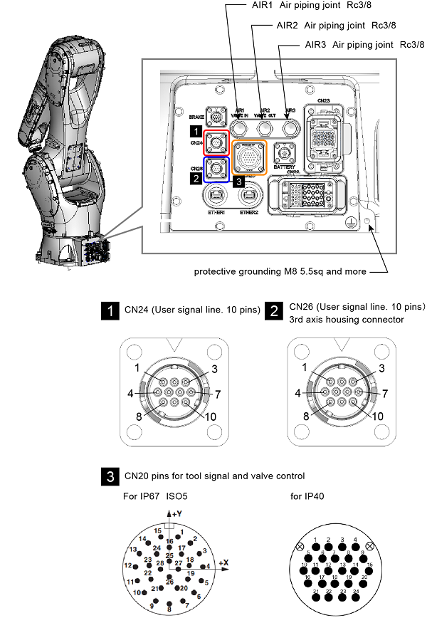
Position and Specification of Each Connector on Connector Panel
| Connector / specifications | Description |
|---|---|
AIR1
|
Supply air to the port of the solenoid valve inside the robot (robot built-in solenoid valve). When supplying air, use dry air filtered by the air filter (recommended filtration degree: 5µm or less). Before piping, blow the air tube out with dry air to clean out the inside (flushing); Otherwise, any chips, cutting oil, dust or dist remaining in the pipe may result in a damaged valve. If the solenoid valve option is not used, it is directly connected to AIR1 on the tool wiring panel. |
AIR2
|
Directly connected to AIR2 on the tool wiring panel. To connect air piping. In the clean room type robot, this functions as an exhaust port of the solenoid valve. |
AIR3
|
Directly connected to AIR3 on the tool wiring panel. To connect air piping. |
CN20Connector specifications on the cable side(CN20 connector)
|
Directly connected to CN21 on the tool wiring panel. To connect signal lines, which is connecting to the tool, to the robot controller or PLC. A connector on the cable side (CN21 connector) connecting to this connector is shipped with a robot unit. However, the CN21 connector is not connected to the cable. Please connect the cable to the CN21 connector on your own. |
CN24Connector specifications on the cable side (CN24 connector)
|
Directly connected to CN25 on the tool wiring panel. To connect signal lines, which is connecting to the tool, to the robot controller or PLC. A connector on the cable side (CN25 connector) connecting to this connector is shipped with a robot unit. However, the CN25 connector is not connected to the cable. Please connect the cable to the CN25 connector on your own. |
CN26Connector specifications on the cable side (CN26 connector)
|
Directly connected to CN27 on the tool wiring panel. To connect signal lines, which is connecting to the tool, to the robot controller or PLC. A connector on the cable side (CN27 connector) connecting to this connector is shipped with a robot unit. However, CN27 connector is not connected to the cable. Please connect the cable to the CN27 connector on your own. |
Pin Assignment on Each Connector
CN20 and CN21
The following table shows pin number correspondence between CN20 and CN21.
Note that the CN20 has pins connecting to the robot built-in solenoid valve, other than pins directly connecting to th CN21.
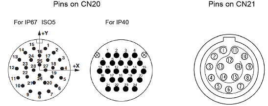
| Pins on CN20 | Pins and solenoid valve input on CN21 (allowable current/allowable voltage) |
|---|---|
| 1 | CN21 -1 (1.0 A / 50 VAC) |
| 2 | CN21 -2 (1.0 A / 50 VAC) |
| 3 | CN21 -3 (1.0 A / 50 VAC) |
| 4 | CN21 -4 (1.0 A / 50 VAC) |
| 5 | CN21 -5 (1.0 A / 50 VAC) |
| 6 | CN21 -6 (1.0 A / 50 VAC) |
| 7 | CN21 -7 (1.0 A / 50 VAC) |
| 8 | CN21 -8 (1.0 A / 50 VAC) |
| 9 | CN21 -9 (1.0 A / 50 VAC) |
| 10 | CN21 -10 (1.0 A / 50 VAC) |
| 11 | CN21 -11 (1.0 A / 50 VAC) |
| 12 | CN21 -12 (1.0 A / 50 VAC) |
| 13 | CN21 -13 (1.0 A / 50 VAC) |
| 14 | CN21 -14 (3.0 A / 50 VAC) |
| 15 | CN21 -15 (3.0 A / 50 VAC) |
| 16 | "Solenoid valve, +24V:NPN / 0V:PNP" |
| 17 | Solenoid valve 1A (Solenoid valve 1) |
| 18 | Solenoid valve 1B (Solenoid valve 1) |
| 19 | Solenoid valve 2A (Solenoid valve 2) |
| 20 | Solenoid valve 2B (Solenoid valve 2) |
| 21 | Solenoid valve 3A (Solenoid valve 3) |
| 22 | Solenoid valve 3B (Solenoid valve 3) |
| 23 | Solenoid valve 4A (Solenoid valve 4) |
| 24 | Solenoid valve 4B (Solenoid valve 4) |
For the connector of CN20 and CN21, use a connector set listed below.
| Connector | Part No. | Model and part name | Appearance |
|---|---|---|---|
| For CN20 (IP40) | 410877-017* |
SRCN6A25-24S (Japan Aviation Electronics Industry Ltd) |
 |
| For CN20 (IP67 / ISO5) | 416137-009* |
HC-26S1N1280DU (manufactured by PHENIX CONTACT) |
 |
| For CN21 (IP40 / IP67 / ISO5) | 416137-008* |
SLKD-16FGMS-GCP-227 (manufactured by Amphenol) |
 |
CN24 and CN25
The following table shows pin number correspondence between CN24 and CN25.
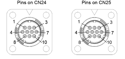
| Pins on CN24 | Pins and solenoid valve input on CN25 (allowable current/allowable voltage) |
|---|---|
| 1 | CN25 -1 (1.0 A / 50 VAC) |
| 2 | CN25 -2 (1.0 A / 50 VAC) |
| 3 | CN25 -3 (1.0 A / 50 VAC) |
| 4 | CN25 -4 (1.0 A / 50 VAC) |
| 5 | CN25 -5 (1.0 A / 50 VAC) |
| 6 | CN25 -6 (1.0 A / 50 VAC) |
| 7 | CN25 -7 (1.0 A / 50 VAC) |
| 8 | CN25 -8 (1.0 A / 50 VAC) |
| 9 | CN25 -9 (1.0 A / 50 VAC) |
| 10 | CN25 -10 (1.0 A / 50 VAC) |
CN26 and CN27
The following table shows pin number correspondence between CN26 and CN27.
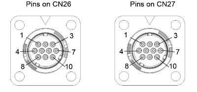
| Pins on CN26 | Pins and solenoid valve input on CN27 (allowable current/allowable voltage) |
|---|---|
| 1 | CN27 -1 (1.0 A / 50 VAC) |
| 2 | CN27 -2 (1.0 A / 50 VAC) |
| 3 | CN27 -3 (1.0 A / 50 VAC) |
| 4 | CN27 -4 (1.0 A / 50 VAC) |
| 5 | CN27 -5 (1.0 A / 50 VAC) |
| 6 | CN27 -6 (1.0 A / 50 VAC) |
| 7 | CN27 -7 (1.0 A / 50 VAC) |
| 8 | CN27 -8 (1.0 A / 50 VAC) |
| 9 | CN27 -9 (1.0 A / 50 VAC) |
| 10 | CN27 -10 (1.0 A / 50 VAC) |
Precautions on Wiring·Piping
The following shows the precautions for wiring and piping.
Noise countermeasure for CN20 and CN21
To connect unrouted wires to the FG line may reduce the noise on the signal lines. However it may increase the leakage current. Please check that the actual conditions on the installation site before connecting.
Ingress protection of Connector
The robot is IP67-rated only when any corresponding plug is connected to the signal line connectors (CN20).
Make a sheathed cable having a suitable diameter ready for use. Using an unsheathed cable cannot assure the splash-proof rating.
Positioning of Gauges
Pressure gauges, oil pressure gauges and other gauges should be installed in an easy-to-check location.
Protection of Electrical Wiring and Hydraulic/Pneumatic Piping
- If there is any possibility of the electrical wiring or hydraulic/pneumatic piping being damaged, protect them with a cover or similar item.
- Be careful not to apply too much pressure on the joint.
ID : 10193
- Related Information
- Solenoid Valve Specifications
- Cable Connection Procedure for CN20 Connector (reference)
- Cable Connection Procedure for CN21 Connector (reference)
- Cable Connection Procedure for CN25, CN24, and CN26 Connectors (reference)
- Cable Connection Procedure for Ether 1, 2 Connector (reference)