
ID : 10195
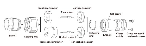
Cable Connection Procedure for CN20 Connector (reference)
For IP40 Rated Model
1
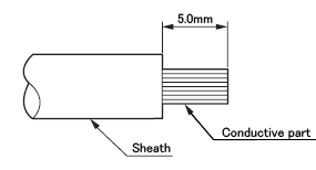
Treatment of wire ends: Strip the wire ends of a customer-prepared cable.
2
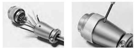
Pass the cable through the end bell and the retaining.
When passing the cable, loose the set screw first, and then remove the end bell from the body.
3
Solder the wires onto the pins.
4
Insert the pins into the coupling nut.
5
Assemble the end bell into the barrel and lock it with the set screw.
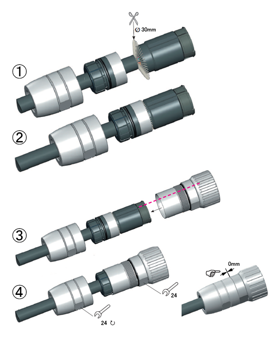
For IP67 Clean Room Type
1
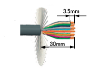
Treatment of wire ends: Strip the wire ends of a customer-prepared cable.
2
Remove the cable clamp part of the housing with a 24mm wrench. Remove the clamp by hand.
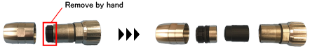
To fit different cable size, the clamp part of the cable clamp consists of several ring layers.
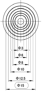
With reference to the following table, adjust the inner diameter of the clamp to the cable being used.
| Gasket inner diameter | φ3 | φ6 | φ8 | φ10 | φ12.5 | φ15 | |
|---|---|---|---|---|---|---|---|
| Outer diameter of the cable (mm) |
min | 2.0 | 2.5 | 4.5 | 6.5 | 9.0 | 11.5 |
| max | 2.5 | 5.5 | 7.5 | 9.5 | 12.0 | 14.5 | |
3
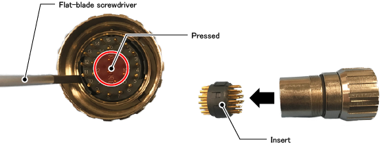
Push in the of the insert with a slot screwdriver and remove the latch. After removing the two latches on both side, remove the insert.
4
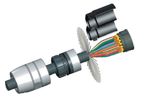
Solder the wires onto the pins.
5
Fit the cable clamp part of the housing, and then tighten up them with 24mm wrench.
ID : 10195