
ID : 10830
Master Setting
Using a GSDML File
GSDML file, which is loaded into the network configurator software, is used to establish, manage, and design networks on your PC.
There are the following two types of GSDML file.
| Type | File name and description |
|---|---|
| Configured GSDML file | GSDML-beckhoff-Conf#el6631-0010.xml |
| This is a GSDML file that the input/output module setting of the robot controller is reflected. This file is created in the robot controller. After loading into the configurator, setting of input/output modules is not necessary. | |
| BECKHOFF general-purpose GSDML file | GSDML-V2.33-beckhoff-EL6631-20181116.xml |
| This is a GSDML file to use EL6631-0010 for general-purpose. Set input/output modules with the configurator. |
When Using a Configured GSDML File
After setting the robot controller, files for PROFINET RT device terminal can be received. When receiving “Digital I/O” data from the robot controller, the data is stored in the project folder of WINCAPSIII. The following shows the destination folder path.
| Folder Path | ...\"Project Name"\Data\Controller\IO\Profinet\ |
|---|
Example of use
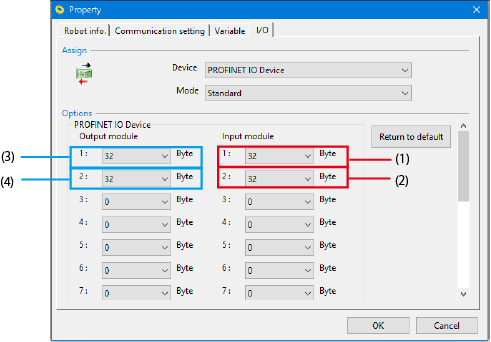
The following example shows when each two modules of input/output modules are configured with 32 bytes.
WINCAPSIII setting
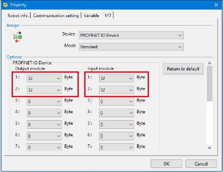
Controller status

When loading into the configurator
Only necessary modules are loaded. The setting with the controller is set to the master as it is.

When Using a General-purpose GSDML File
After loading a general-purpose GSDML file, set input/output modules with the configurator.
Procedure
1
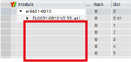
Select “EL6631-0010 V2.33, at least FW 14” from several devices.

Module configuration slots are empty.
2
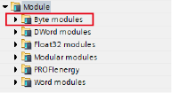
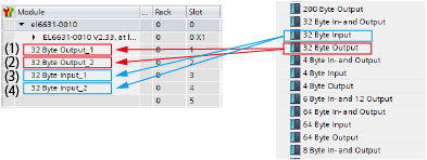
Select “Byte modules” from module type.
3
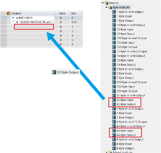
From “Byte modules” list, drag a byte number that you want to set and drop to an empty slot.
Select “32 Byte Input” or “64 Byte Input” for input, “32 Byte Output” or “64 Byte Output” for output.
4
Repeat STEP3 for the necessary number. You can set maximum of 15 modules for both input/output.
Set output modules in order from 1, and then set input modules in order from 1. (Refer to the following example.)
Setting example
The following example shows when each two modules of input/output modules are configured with 32 bytes.
Set one by one for the number of necessary modules.
WINCAPSIII setting
Configurator setting
ID : 10830