
ID : 10970
Enable Auxiliary Axes
To use the auxiliary axis function, you need to enable an auxiliary axis in a robot project.
You can enable the auxiliary axis through the following two methods.
Create a new project
Use WINCAPSIII to create a new project.
Select “Use” on the controller option selection window, which is displayed while the program is being created.
For how to activate WINCAPSIII and create a new project, refer to this page.
Enable auxiliary axes in the existing robot project
1
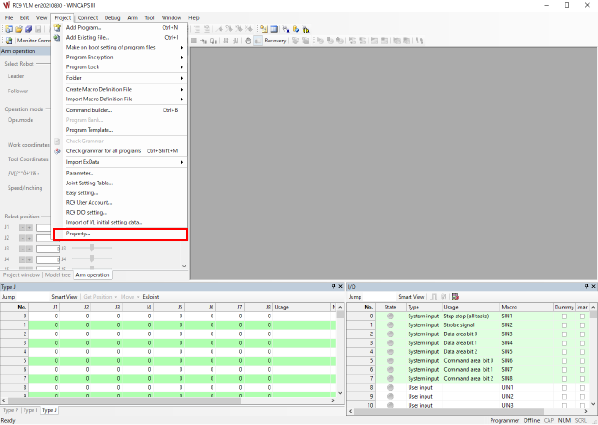
Select [Property] in the [Project] tab in WINCAPSIII.
2
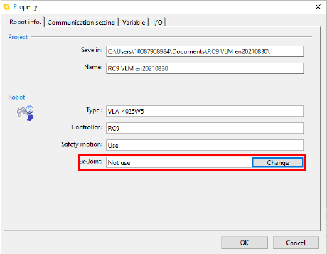
After [Property] appears, select [Change] in the Ex-joint box to change the status to “Use”.
To add auxiliary axes to the robot in use, obtain a project from the RC9 robot controller in use to enable them.
Add auxiliary axes to the robot in use
1
Obtain from the RC9 robot controller the project of a robot to which you intend to add auxiliary axes.
2
Enable the auxiliary axis setting in the project.
For how to enable the auxiliary axis setting, refer to this page.
3
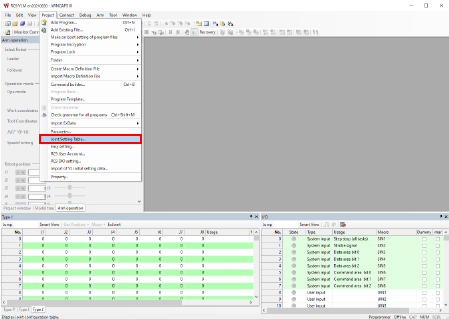
Select [Joint Setting Table] in the [Project] tab in WINCAPSIII.
4
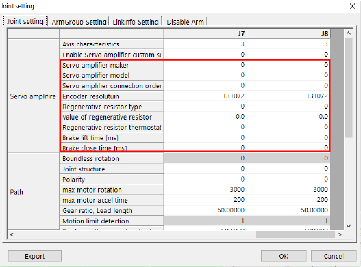
Open the [Joint Setting] tab on the [Joint Setting] screen and set the parameters for the axis to be used as an auxiliary axis.
In this tab, set the following parameters.
These parameters can be set only through WINCAPSIII.
For details of the parameters, refer to Servo Amp Parameter Setting.
| Description |
|---|
Servo amplifier makerDetermines the maker of the servo amplifier to be connected. |
Servo amplifier modelDetermines the model of the servo amplifier to be connected. |
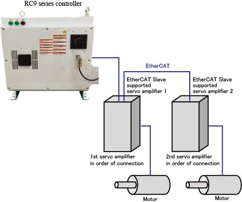
Servo amplifier connection orderServo amplifier connection order is a parameter that determines which servo amplifier in order of connection starting with the one nearest to the RC9 controller will be linked to the enabled axis among the amplifiers connected to the controller in the daisy chain.When servo amplifiers are connected as shown below, the following settings are possible.
Setting values for J7 and J8 can be switched as shown below.
If you specify duplicate values for Servo amplifier connection order or fail to set values in order from smaller numbers, unintended axes may start moving. For details, refer to [Servo Amp Parameter Setting]. |
Encoder resolutionDetermines the encoder resolution to be used for the connected servo amplifiers. |
Regenerative resistor typeSelect the state of the regenerative resistor from the following items.
|
Value of regenerative resistorDetermines a resistance value of the regenerative resistor. |
Regenerative resistor thermostat input portDetermines the port for the regenerative resistor thermostat input. |
Brake lift timeDetermines the delay time for the operation of the holding brake when a holding brake circuit is used. |
Brake close timeDetermines the delay time for releasing the holding brake when a holding brake circuit is used. |
Setting Servo amplifier connection order improperly can cause unintended axes to start moving.
5
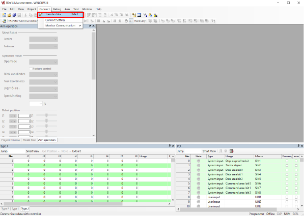
After setting the parameters properly, press [Transfer data] to send [Arm Parameters] to the RC9 robot controller in use.
Select [Transfer data] in the [Connect] tab in WINCAPSIII.
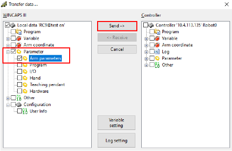
Select [Parameter] - [Arm Parameters] in the [Transfer data] window, then press the [Send] button.
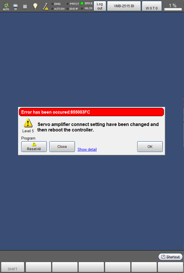
After the transfer is complete, the window below appears on the smart TP. Press [OK], then turn off the RC9 robot controller.
6
Connect the servo amplifier to the RC9 controller.
For how to connect them, refer to this page.
7
Turn on the RC9 robot controller.
ID : 10970