
ID : 11086
Additional Setting of 4-Axis or 6-Axis Robots
Robot Series and Supported Version
| Name | Robot series | Supported version | ||
|---|---|---|---|---|
| XYZT | 4-Axis XYZT robot | Ver.1.2 | ||
| H | 4-Axis SCARA robot | Ver.1.2 | ||
| XR | 4-Axis XR robot | Ver.1.2 | ||
| DLT4 | 4-Axis parallel link robot | Ver.1.2 | ||
| 6-Axis Type A | 6-Axis Type A robot | Ver.1.2 | ||
| 6-Axis Type B | 6-Axis Type B robot | Ver.1.2 | ||
Overview
For 4-Axis Robots
When using a ball screw spline to the linear motion axis on a 4-axis robot, additional parameter settings are required.
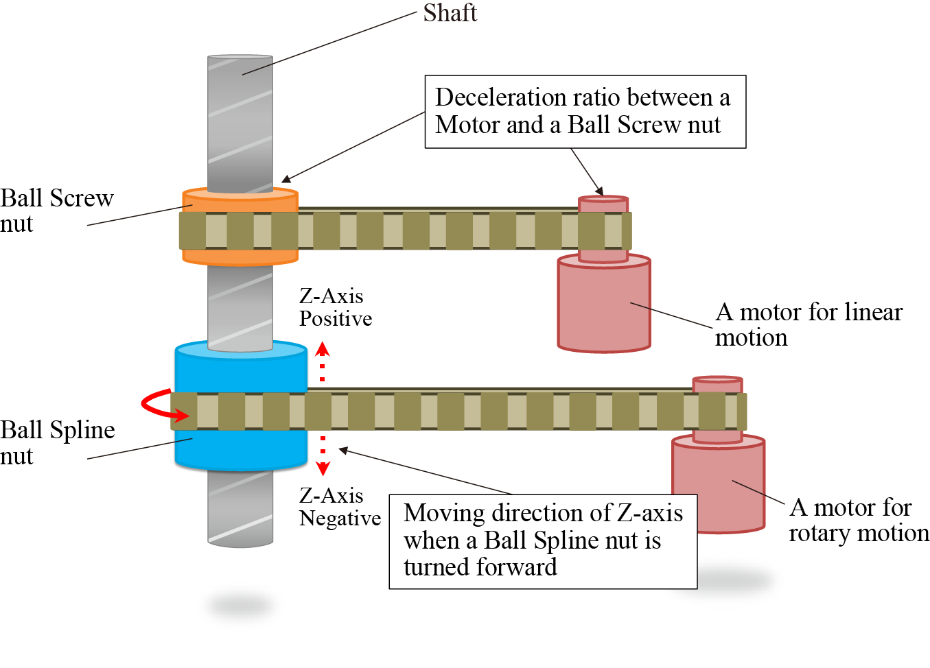
The ball screw spline is structured with the "ball screw nut", the "ball spline nut", and the "shaft" as shown in the figure below. When rotating the ball screw nut, the shaft performs a linear motion; when rotating the ball spline nut, the shaft performs a linear motion while rotating.
To rotate only the shaft, rotate the ball screw nut and the ball spline nut at the same time. At that time, the following two parameters need to be set for calculating the rotation and the rotary direction of the ball screw nut to the rotation of the ball spline nut.
- Deceleration ratio between Motor Shaft and Ball Screw nut
- To which direction of Z-axis of the base coordinate does the shaft move if rotating the ball spline nut to the direction where the robot flange rotates in normal direction?
For 6-Axis Robots
For 6-axis Type A robot, the mechanism that the 6th-axis moves according to the motion distance of 5th-axis is available. In this case, the following two parameters need to be set.
- Differential gear ratio
- 6th-axis moving direction at the 5th-axis forward direction rotation
Setting Procedures
If the robot type selected by the Kinematics Configuration Tool has any parameters that can be additionally set, the additional setting item will be displayed in the arm length setting.
For 4-Axis Robots
Selecting [Use] in the [Ball Screw Spline] setting enables to set additional parameters. The following shows the setting window of the 4-axis SCARA robot as a sample.
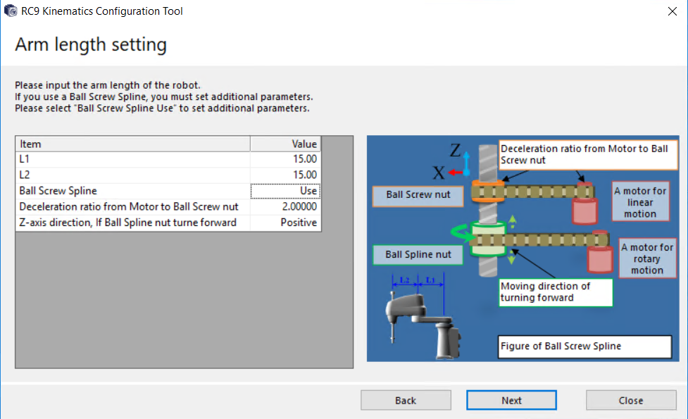
- Execute this setting only when using a "ball screw spline". If executing this setting not for using a ball screw spline, the robot may operate unintentionally.
- If the setting differs between the design value and parameters, the robot may operate unintentionally. Make sure of the setting.
For 6-Axis Robots
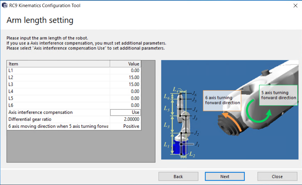
Selecting [Use] in the [Axis interference compensation] setting enables to set additional parameters.
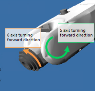
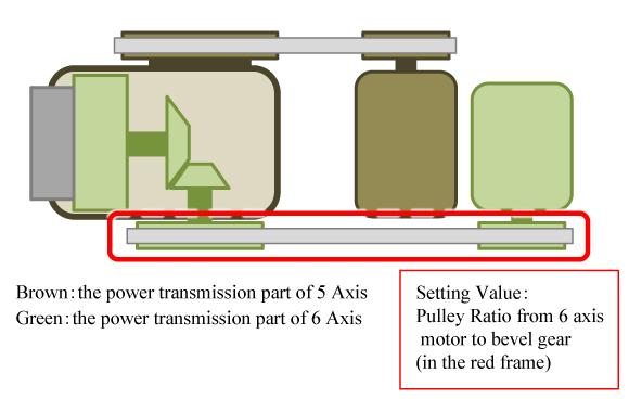
As an example, the following shows the case that bevel gears are used in a drive mechanism of the 6th-axis.
In the following figure, the 6th-axis motor is placed on the second arm side and the drive force is transmitted to the 6th-axis output through the belt, bevel gears, and deceleration device (the green colored part). In this structure, when the 5th-axis, which is colored with brown, moves, the bevel gear-contact part gives the motion. As a result, the 6th-axis rotates even if the 6th-axis motor is standstill. To enable the Axis interface compensation setting will correct the 6th-axis rotation so as not to give the 5th-axis rotation.
For [Differential gear ratio], enter the ratio of the pulleys enclosed with the red square. For [6 axis moving direction when 5-axis turning forward direction], select "Positive" when the 6th-axis rotates in positive direction along with the 5th-axis positive rotation, for other case, select "Negative".
- Do not perform this setting unless it is necessary. For example, if this setting is made when the ball screw spline shaft is not used in 4-axis robot, the robot may perform unintended behavior.
- If the setting differs between the design value and parameters, the robot may operate unintentionally. Make sure of the setting.
Limits of Setting
For 4-Axis Robots
"Deceleration ratio between Motor Shaft and Ball Screw nut" can be set exclusively with the larger values than 0.
For 6-Axis Robots
For [Differential gear ratio], only a value higher than 0 can be entered.
ID : 11086