
ID : 874
1st-axis Mechanical End Change
At the time of delivery from the factory, mechanical ends are set in the VM-6083/VM-60B1 series so that the stroke of the 1st axis will be ±170°.
Changing the mechanical ends of the 1st axis by adding mechanical stops is called a mechanical end change.
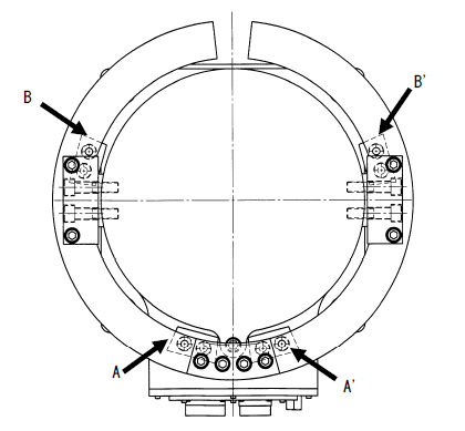
The figure below shows the mechanical stop positions for mechanical end change.
Given below is an example when the mechanical stops are positioned as specified in the table below.
To change the mechanical ends, the following four types of mechanical stop parts are required.
- Mechanical stop (4 pieces) - Fixture block A (2 pieces) - Fixture block B (1 piece) - Plate (2 pieces)
The figures on the following pages show the drawings of those mechanical stop parts. Referring to those drawings, you should prepare mechanical stop parts as necessary so that your desired motion space may be set.
If the 1st axis comes into contact with any mechanical stop because of the width of the stopper and its bolt, the angle of the 1st axis is different between the positive and negative directions. The table below shows the angles of the 1st axis in the positive and negative directions when it is in contact with each mechanical stop.
Stroke of the 1st Axis to Mechanical Ends
| Mechanical stop position | Positive direction | Negative direction |
|---|---|---|
| A | 5° | 28°45’ |
| A’ | -28°45’ | -5° |
| B | 95° | 118°45’ |
| B’ | -118°45’ | -95° |
| Permanent mechanical end | 170° | -170° |
ID : 874