
ID : 2967
Device Control
Device control of a robot controller is performed as shown the following chart; and its state is controlled with Controlword(J1)-(J8)(Index:0x6040,0x6840,0x7080,0x7880,0x8080,0x8880,0x9080,0x9880).
Device state of the robot controller is able for monitoring by using Statusword(J1)-(J8) (Index:0x6041,0x6841,0x7081,0x7881,0x8081,0x8881,0x9081,0x9881).
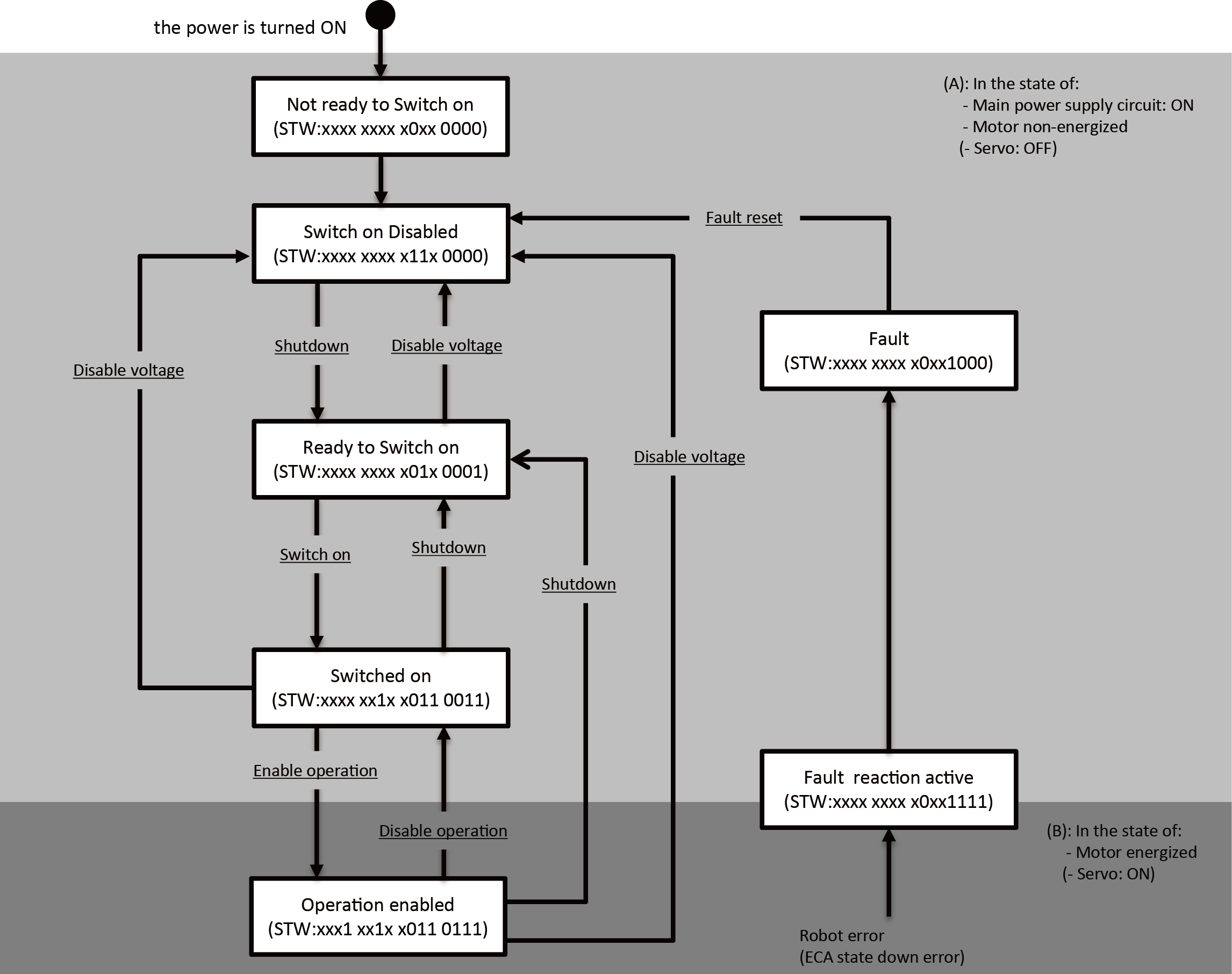
- The characters in the white boxes show the states.
- STW shows Statusword (J1)-(J8) (Index:0x6041,0x6841,0x7081,0x7881,0x8081,0x8881,0x9081,0x9881) Statusword (J1)-(J8) has the same values. The joint disabled in the "Joint enable/disable setting" is 0-fixed.
- The under lines of each words perform as the control command of Controlword(J1)-(J8) (Index:0x6040,0x6840,0x7080,0x7880,0x8080,0x8880,0x9080,0x9880). All the joints' states can transition according to the changes of control command of only one joint, which is among the joints enabled at the "joint setting enabled/ disabled". (All the joints' statuses can transition according to the logical conjunction of Controlword at every joint.)
- If the joints have different Controlword, the smallest numbers of joint will be prioritized. e.g., If the numbers of Controlword(J1) is different from that of Controlword(J2), Controlword(J1) will be prioritized.
Controlword Bit ( State Machine Control Code)
| Bit | State | Description |
|---|---|---|
| 0 | Switch on | Refer to Details on "Bit 0 to 3, 7 " below. |
| 1 | Enable voltage | |
| 2 | Quick stop | |
| 3 | Enable operation | |
| 4 | - | Reserved |
| 5 to 6 | Cycle counter | Refer to Details on "Bit 5, 6" below. |
| 7 | Fault reset | 0→1: Error reset Refer to Details on "Bit 4 to 9" below. |
| 8 to 15 | - | Reserved |
Details on Bit 0 to 3, 7
| Command | Controlword Bit | ||||
|---|---|---|---|---|---|
| Bit 7 | Bit 3 | Bit 2 | Bit 1 | Bit 0 | |
| Shutdown | 0 | X | X | 1 | 0 |
| Switch on | 0 | 0 | X | 1 | 1 |
| Switch on + Enable operation | 0 | 1 | X | 1 | 1 |
| Disable voltage | 0 | X | X | 0 | X |
| Disable operation | 0 | 0 | X | 1 | 1 |
| Enable operation | 0 | 1 | X | 1 | 1 |
| Fault reset | 0->1 | X | X | X | X |
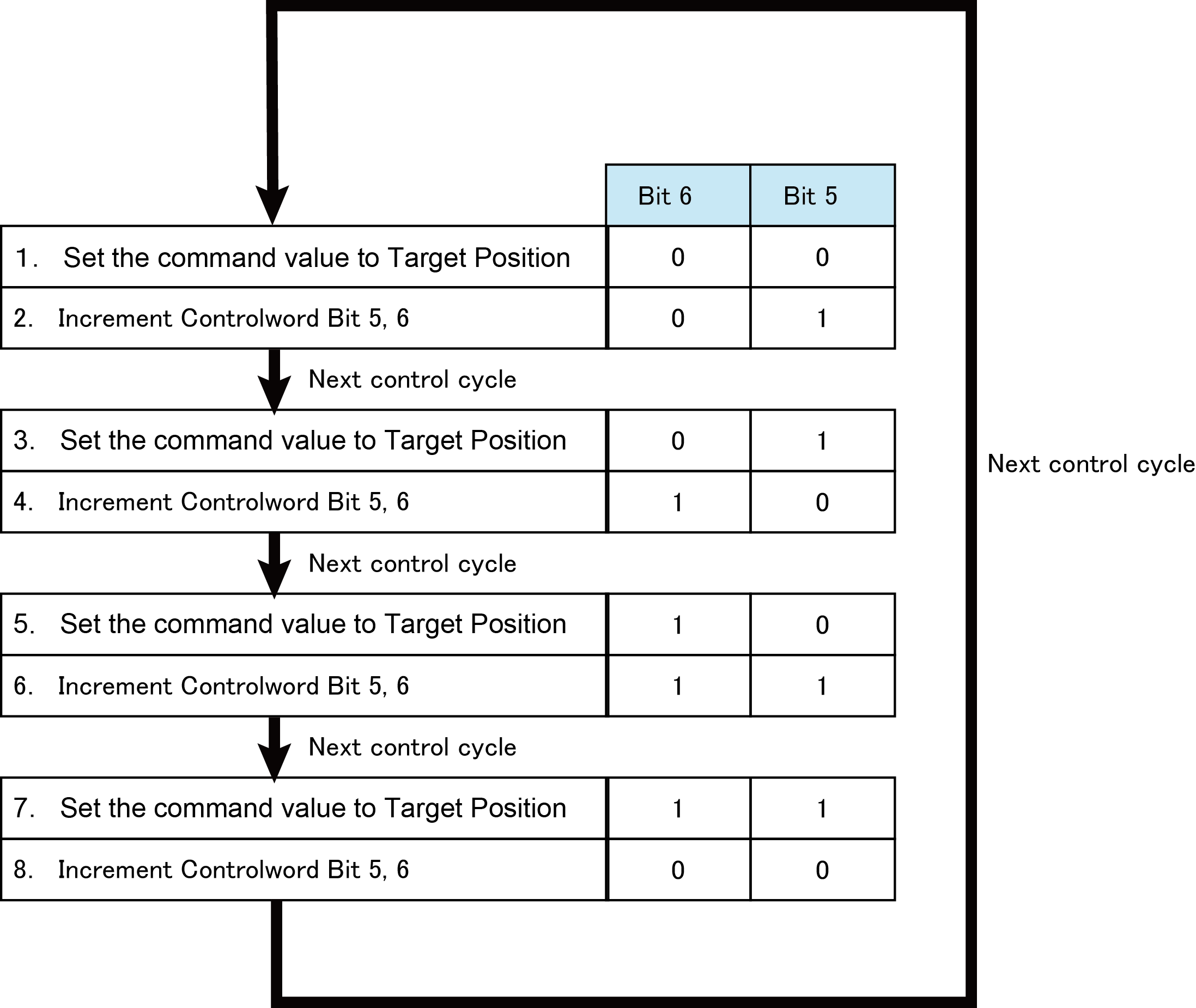
Details on Bit 5, 6
If you set Synchronization option to Enable notification, the command interpolation in the robot controller, which is as Slave, can be possible by changing the following numbers to Cycle counter, Bit 5 and 6.
Whenever updating command values with the controller which has EtherCAT Master function, by which trajectory can be created, be sure to increment a value of Cycle counter. When communicating with 250us and 500us, this processing is a must.
Statusword Bit
| Bit | State | Description |
|---|---|---|
| 0 | Ready to switched on | Refer to Details on "Bit 0 to 7" below. |
| 1 | Switched on | |
| 2 | Operation enabled | |
| 3 | Fault | |
| 4 | Voltage enabled | |
| 5 | Quick stop | |
| 6 | Switch on disabled | |
| 7 | Warning | |
| 8 | - | Reserved |
| 9 | Remote | Controlword is dealt with |
| 10,11 | - | Reserved |
| 12 | Drive follows the command value | 0: Disable command 1: Enable command |
| 13,14 | - | Reserved |
| 15 | Critical error | 0: Level 5 error does not occur 1: Level 5 error occurs |
Details on Bit 0 to 7
| Bit | Bit | Bit | Bit | Bit | Bit | Bit | Bit | State of the drive |
|---|---|---|---|---|---|---|---|---|
| 7 | 6 | 5 | 4 | 3 | 2 | 1 | 0 | |
| X | 0 | X | X | 0 | 0 | 0 | 0 | Not ready to switch on |
| X | 1 | 1 | X | 0 | 0 | 0 | 0 | Switch on disabled |
| X | 0 | 1 | X | 0 | 0 | 0 | 1 | Ready to switch on |
| X | 0 | 1 | X | 0 | 0 | 1 | 1 | Switch on |
| X | 0 | 1 | X | 0 | 1 | 1 | 1 | Operation enabled |
| X | 0 | X | X | 1 | 1 | 1 | 1 | Fault reaction active |
| X | 0 | X | X | 1 | 0 | 0 | 0 | Fault |
| X | X | X | 1 | X | X | X | X | Main power on |
If level 5 error occurs in the robot controller (Statusword bit 15 is 1), you cannot clear the error from the external device that is EtherCAT master. Confirm its error description by connecting a teach pendant or with the monitor function of WINCAPSIII, and solve the cause of the error.
ID : 2967