
ID : 2973
Additional Setting Parameters of Parallel Link Robot
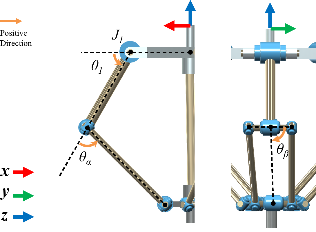
When selected a parallel link robot as robot type, the motion range of θα, θβshown in the figure as well as the limits of motion range of the motor shaft angle (θ1) need to be set for a breakage prevention of the elbow portion.
Operation Procedure
Display Config screen by following the procedure shown below and set parameter.
Operation path : [F2 Arm] - [F6 Aux] - [F1 Config]
θα Motion Range
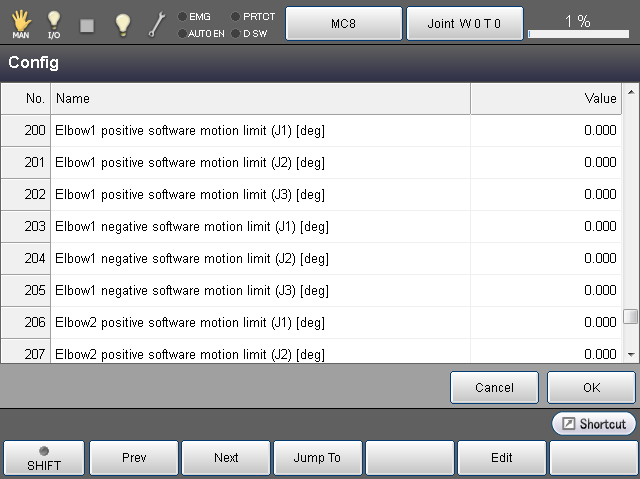
Set θα motion range by the following parameter.
| No. | Item Name |
|---|---|
| 200 | Elbow 1 positive software motion limit (J1)[deg] |
| 201 | Elbow 1 positive software motion limit (J2)[deg] |
| 202 | Elbow 1 positive software motion limit (J3)[deg] |
| 203 | Elbow 1 negative software motion limit (J1)[deg] |
| 204 | Elbow 1 negative software motion limit (J2)[deg] |
| 205 | Elbow 1 negative software motion limit (J3)[deg] |
θβ Motion Range
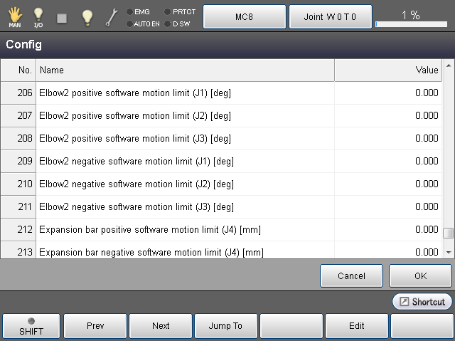
Set θβ motion range by the following parameter.
| No. | Item Name |
|---|---|
| 206 | Elbow 2 positive software motion limit (J1)[deg] |
| 207 | Elbow 2 positive software motion limit (J2)[deg] |
| 208 | Elbow 2 positive software motion limit (J3)[deg] |
| 209 | Elbow 2 negative software motion limit (J1)[deg] |
| 210 | Elbow 2 negative software motion limit (J2)[deg] |
| 211 | Elbow 2 negative software motion limit (J3)[deg] |
4 Axis Parallel Link Robot
When selected 4 axis parallel link robot as robot type, the telescoping bar's maximum and minimum values shown in the figure need to be set because the power transmission part is expansion mechanism.
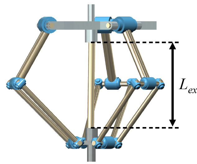
Set Lex with the following parameter.
| No. | Item Name |
|---|---|
| 212 | Telescoping bar positive software motion limit (J4)[mm] |
| 213 | Telescoping bar negative software motion limit (J4)[mm] |
ID : 2973