
ID : 3458
Example of Making Reversal Assistance Jig
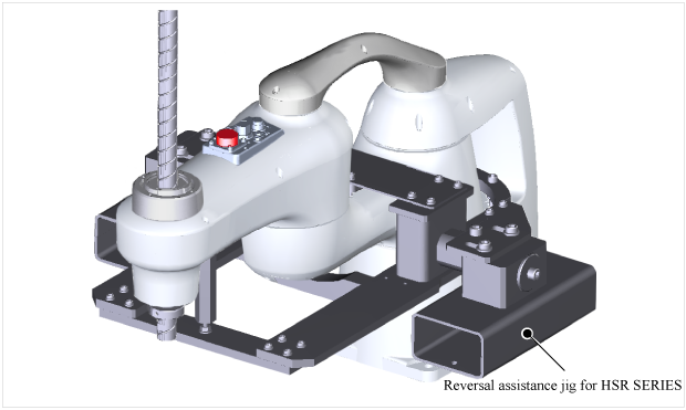
This section describes an example of a reversal assistance jig required to mount the robot overhead.
Make a reversal assistance jig as shown in the figure below to reverse the HSR series robot for overhead-mount.
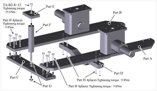
1
Assemble the part A to H as shown in the figure below. Make each part, referring to the reference drawings shown in the table below.
| 番号 | 参考図 |
|---|---|
| Part A |
PLATE (Reference Drawing(PDF:678KB)) |
| Part B |
PLATE (Reference Drawing(PDF:614KB)) |
| Part C | PLATE (Reference Drawing(PDF:132KB)) |
| Part D | PLATE (Reference Drawing(PDF:136KB)) |
| Part E | BRACKET (Reference Drawing(PDF:3,902KB)) |
| Part F | HEXAGON SUPPORT MISUMI Corporation: part number PLSBH24-115-F40-M8-N8 (Reference Drawing(PDF:88KB)) |
| Part G | NUT MISUMI Corporation: part number FRNUT8 ((PDF:246KB)) |
| Part H | FLANGE SOCKET M6 × 25 MISUMI Corporation: part number 070006025 ((PDF:207KB)) |
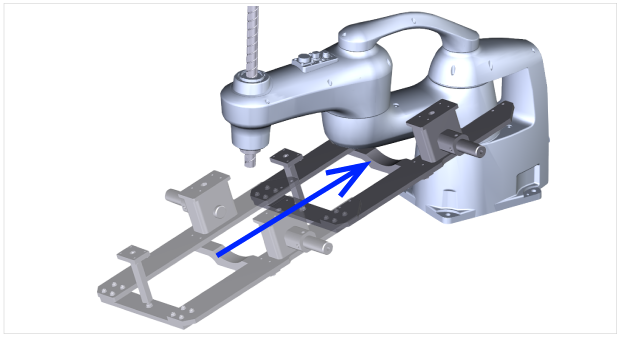
2
Install the jig assembled in STEP 1 to the robot carefully not to collide with the T-axis of the robot.
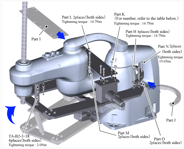
3
Fix the robot and the jig assembled in STEP 1 with bolts and the part I to O.
| 番号 | Item/Reference Drawings |
|---|---|
| Part I |
|
| Part J | BRACKET (Reference Drawing (PDF:121KB)) |
| Part K |
|
| Part L |
|
| Part M | COLLAR : inner diameter 6.5L13.5 : 2 places MISUMI Corporation: part number DWSSM-D14.5-V6.5-L13.5 ((PDF:419KB)) |
| Part N | BOLT MISUMI Corporation: part number CB8-35 ((PDF:86KB)) |
| Part O |
COLLAR : inner diameter 8.5L8 : 2 places MISUMI Corporation: part number DWSSM-D15-V8.5-L8 ((PDF:236KB)) |
4
Install the part P and Q to the jig assembled in STEP 3. Make each part, referring to the reference drawings shown in the table below.
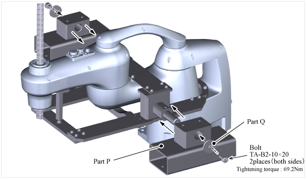
| 番号 | 参考図 |
|---|---|
| Part P | |
Part Q |
COVER(Reference Drawing (PDF:102KB)) |
5
Fix the part Q assembled in STEP 4 with bolts and the part R. Make each part, referring to the reference drawings shown in the table below.
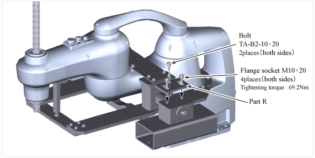
| 番号 | 参考図 |
|---|---|
| Part R |
ID : 3458