
ID : 4873
System Components
Configuration of the Robot System
An extended-joint support system can be configured (see the illustration given below) by using a robot controller designed for extended-joint motors to be connected and connecting the following options.
-
Extended-joint motors which are equipped with bus-line encoders.
(6-axis robot: up to 2 motors. 4-axis robot: up to 4 motors. motor type selectable) - Encoder Hub
- Motor Cable
- Encoder Cable
- Encoder Backup Battery
- Connected SLOT number is different depending on the motor combination in use.
- The portion to connect the SLOT is described on "the label placed on the upper side" of the controller. Please carefully confirm the label when connecting.
- For about precautions on cable connection, see "Caution for Wiring".
- The total length of an encoder cable for each axis between a connection port of the encoder hub and a connection port of the motor shall be 16meter or less. The total length of a motor cable of each axis between a connection port of the controller and a connection port of the motor shall be 16meter or less. The total length of all axes on the Extended-joint is 48m. The maximum length of the Motor & Encoder cable is 12m.
- Components used in this system are not Dust- & Splash-proof type. These components can not be used in the environment which requires Dust- & Splash-proof type.
Models Except UL-Listed Ones
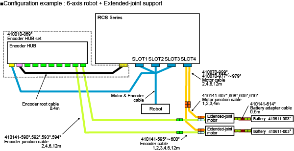
Please refer to this if the figure is not clear. (PDF:214KB)
UL-Listed Model
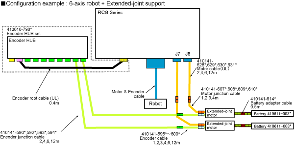
Please refer to this if the figure is not clear. (PDF:243KB)
Variation of the Extended-Joint Motors
| Brake | 30W | 50W | 100W | 200W | 400W | 750W | 1.0kW |
|---|---|---|---|---|---|---|---|
| With | ◯ | ◯ | ◯ | ◯ | ◯ | ◯ | ◯ |
| Without | ◯ | ◯ | ◯ | ◯ | ◯ | ◯ | ◯ |
ID : 4873