
ID : 4881
Connect Cables to the Robot Controller
A hook-up example of the extended-joint support system is illustrated below. Refer to the diagram below when connecting.
Connection Diagrams
Models Except UL-Listed Ones
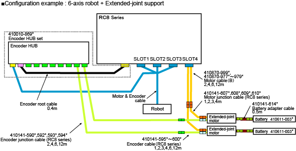
Please refer to this if the figure is not clear. (PDF:215KB)
Connect to Encoder Hub
For encoder hub, there are old model and new model.
If you use a new model, connect the encoder line of the motor & encoder cable to the encoder hub's connector port indicated as "ROBOT-0" (on the left side viewed from the front).
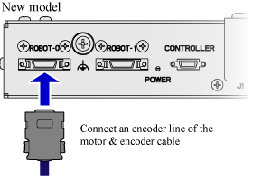
For details about the external diagram and the precaution on installation, refer to "Encoder HUB".
UL-Listed Model
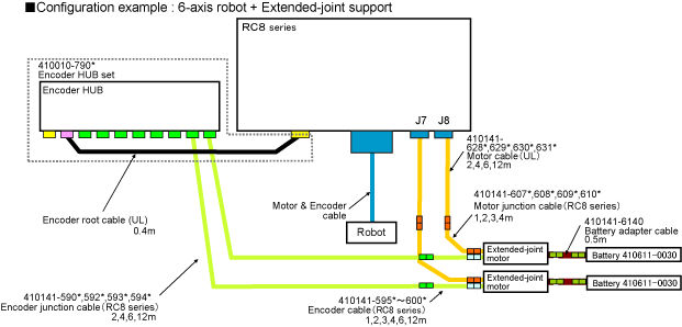
Please refer to this if the figure is not clear. (PDF:243KB)
Caution for Wiring
-
Use DENSO WAVE-authorized extended-joint cables.
Never modify those cables or use cables other than DENSO WAVE-authorized ones to configure an extended-joint support system. -
Miswiring of extended-joint cables could cause malfunction the motors.
To prevent miswiring of extended-joint motors, attach the labels that come with a set of extended-joint cables to those cables. - Controller, Cable and Cable connector parts are not dust-& splash-proof. If you use them in any environments where the ingress of dust or liquid may occur, please take appropriate ingress prevention measures.
- Be sure to connect all of the shield wires of the motor cables and encoder cables and the FG wires of the motors to ground. Connect ring terminals of each cable to the earth terminal of the enclosure
- For safety reason and to prevent damage to the devices, disconnect the power cable of the controller or shut down the power supply to the controller from the facilities before disconnecting or connecting cables.
- Connected SLOT number is different depending on the motor combination in use.
- The portion to connect the SLOT is described on "the label placed on the upper side" of the controller. Please carefully confirm the label when connecting.
- For about precautions on cable connection, see "Caution for Wiring" .
-
The total length of an encoder cable for each axis between a connection port of the encoder hub and a connection port of the motor shall be 16meter or less. The total length of a motor cable of each axis between a connection port of the controller and a connection port of the motor shall be 16meter or less.
For the Extended-joint, the total length of the motor cable of all axes on the Extended-joint is 48m. The maximum length of the Motor & Encoder cable is 12m. For the MC8, the total length of all axes is 96m a the maximum. - The bending radius for the encoder cable and encoder relay cable should be 12.5 mm or more for the fixed cable, and 83 mm or more for the movable cable. The bending radius for the motor cable and the motor relay cable should be 13.5 mm or more for the fixed cable, and 90 mm or more for the movable cable. Excessive bending will damage the cable.
-
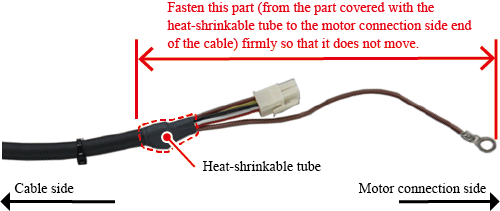
To prevent the cable from breaking, observe the following precautions for use of the encoder cable and motor-junction cable.
Encoder cable
Two encoder cable models, the old model and the new model, require different precautions.
Old model
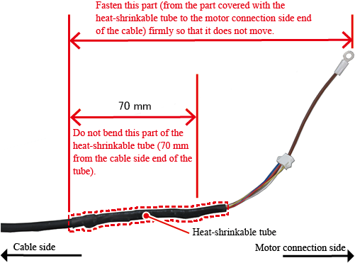
New model
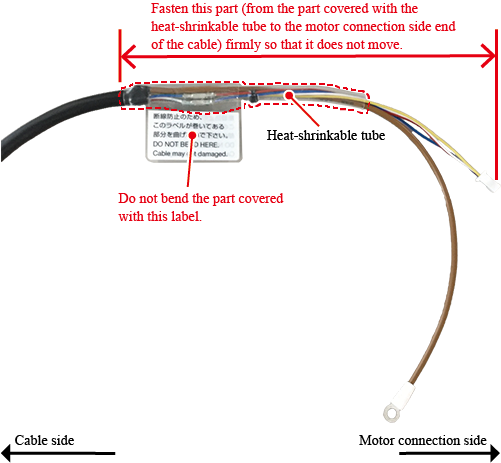
Motor junction cable
ID : 4881
- Related Information
- Encoder Backup Battery
- Caution for Wiring