
ID : 5105
Visual Calibration Procedure with a TP Panel
This document describes about the procedure of using the provided operation panel to easily perform "Vision - robot coordinate calibration" between the RC8 series robot controller and the visual device.
Data must be imported to your controller to use the calibration operation panel.
For the importing mehod, refer to PC SOFTWARE > WINCAPSIII GUIDE > Writing Programs > Leveraging Existing Files in the manual.
Preparation
- From the links in the table below, download the robot programs and BMP files and import them into your RC8 series robot controller.
Type Data Operation panel for calibration Calibration.pns (PNS:27KB)
CalResult.pns (PNS:9KB)
HelpRob.BMP (BMP:998KB)
HelpVis1.BMP (BMP:998KB)
HelpVis2.bmp (BMP:749KB)
HelpVis3.bmp (BMP:749KB)
Main.pns (PNS:601B)
UserPanel.pns (PNS:352B) -
If your visual device is a product of one of the following four manufacturers, vision coordinates can automatically be entered with centroid detection.
Other visual devices can be used by manually entering vision coordinates.
For supported visual devices, copy the robot program (TSR10.pcs) and visual program of each manufacturer; and then import the robot program and the visual program into the robot controller and an each manufacturer's visual device, respectively. The robot program TSR10.pcs is a robot program designed to receive data from a visual device.
Start the operation panel after starting the robot program (TSR10.pcs).
Manufacturer Product Data KEYENCE XG series inspect.dat (DAT:7KB)
TSR10.pcs (PCS:969B)OMRON FZ series calibration.scn (SCN:6KB)
TSR10.pcs (PCS:875B)Cognex In-Sight series 3PointCal.job (JOB:47KB)
TSR10.pcs (PCS:2KB)Panasonic Industrial Devices SUNX PV series Set00.PV2 (PV2:126KB)
TSR10.pcs (PCS:1,004B) -
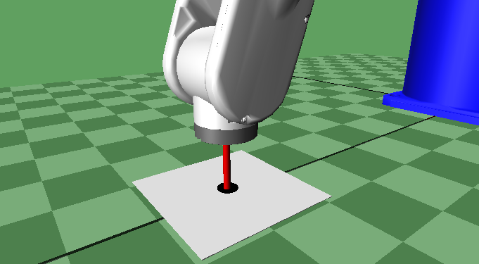
Prepare a calibration jig (with a mark printed).
The visual program determines the centroid position of a circle. Prepare marks with a cross in the centroid position (refer to the following figures) to make it easier to align the position of the robot tool with the centroid position.
Example of a mark 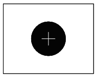
ID : 5105
- Related Information
- Operation Panel Screen
- Procedure of the calibration