
ID : 5380
Configuration of the Conveyor Tracking System with One Conveyor and Two or more Robots
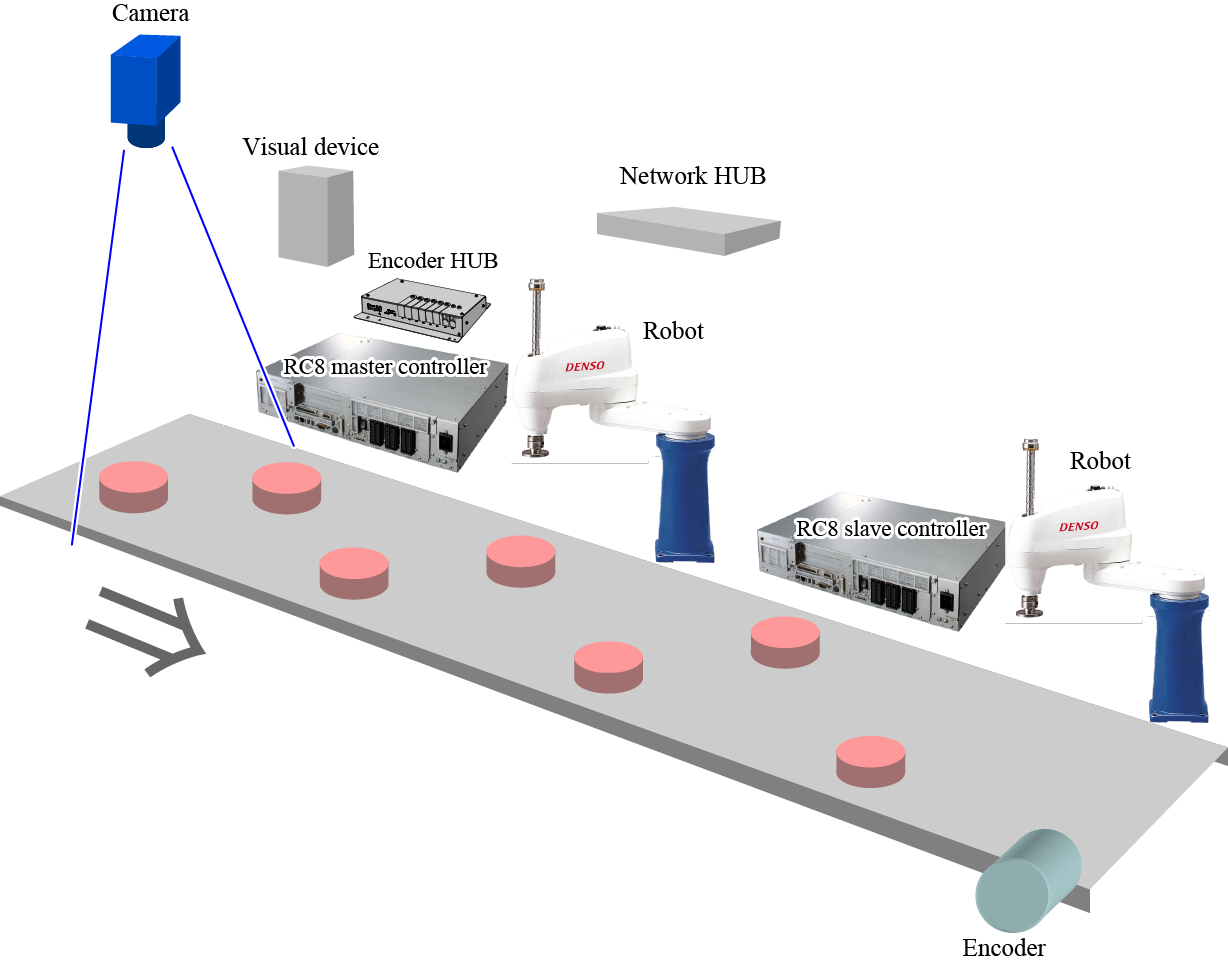
The example of the vision tracking system is illustrated below.
This system configuration is effective in the case where the conveyor moves so fast that one robot is not enough to pick up all workpieces. Up to three slave controllers are available.
In this application, one controller is designated as a master controller, and the remaining controllers are designated as slave controllers.
The master controller is connected to the visual device and the encoder. This controller obtains position data of workpieces and then executes picking up operation by robot.
The slave controller connects to the master controller with Ethernet cable. This controller executes program to pickup workpieces based on the position data obtained by the master controller.
Conveyor Tracking
- When you install two or more robots in one system, arrange these robots so as not to interfere each other.
- The specifications for the master controller and slave controllers must be the same. All of them must have the conveyor tracking licenses, and must be set to Extended-joint-supported, and the same software version.
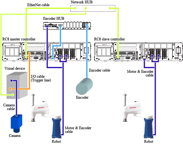
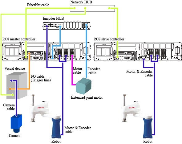
Wiring Diagram
Wiring diagram is illustrated below.
Encoder Hub
For encoder hub, there are old model and new model.
If you use a new model, connect the encoder line of the motor & encoder cable to the encoder hub's connector port indicated as "ROBOT-0" (on the left side viewed from the front).
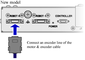
For details about the external diagram and the precaution on installation, refer to "Encoder HUB".
Extended-joint Tracking
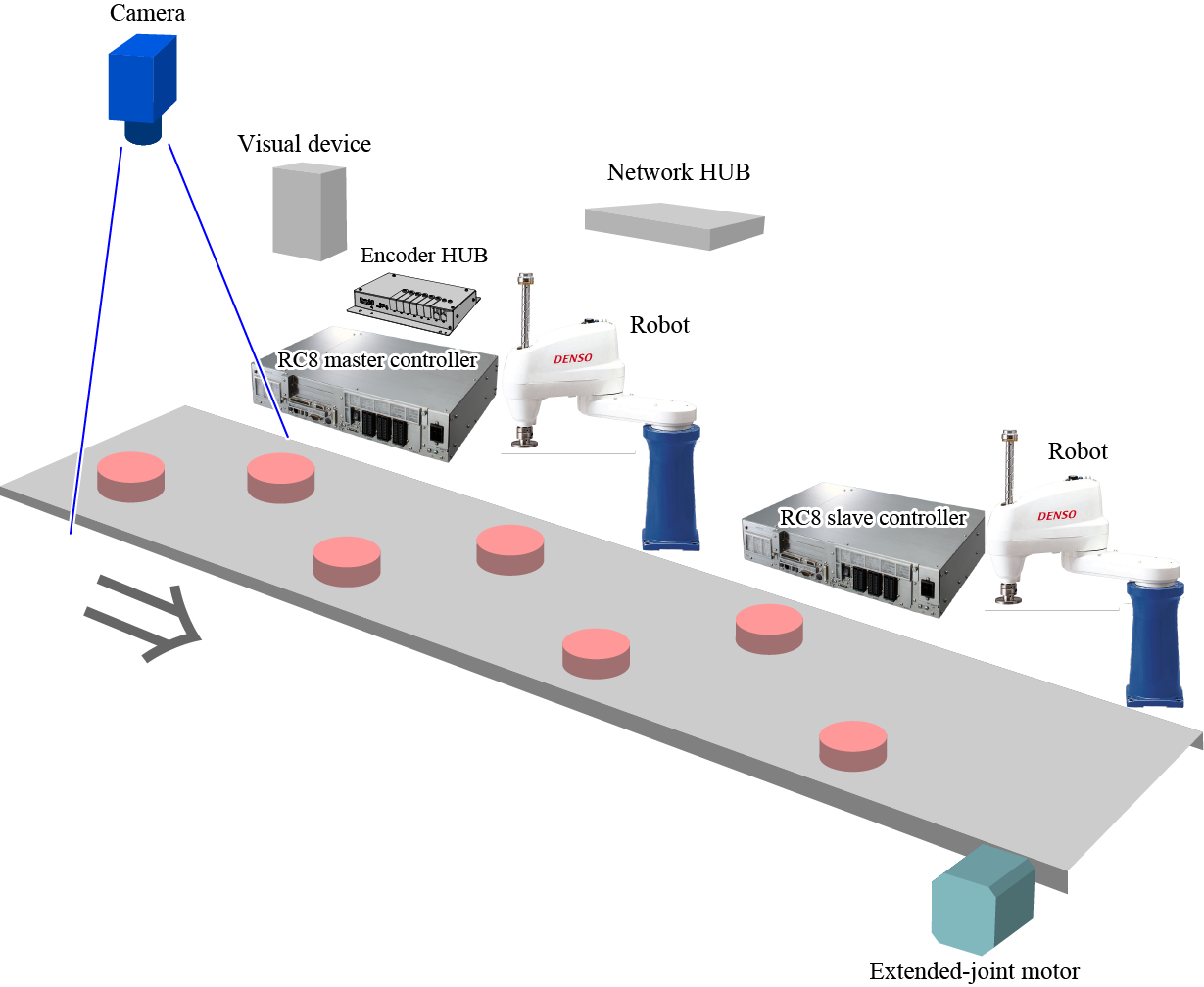
Wiring Diagram
The master controller and the slave controller must have the same specifications. (Extended-joint equipped, extended-joint tracking license-registered, use the same software version).
Encoder Hub
For encoder hub, there are old model and new model.
If you use a new model, connect the encoder line of the motor & encoder cable to the encoder hub's connector port indicated as "ROBOT-0" (on the left side viewed from the front).
For details about the external diagram and the precaution on installation, refer to "Encoder HUB".
ID : 5380