ID : 1692
Basic Screen and Icons
Command for Teach Pendant
Various screens can be displayed on the liquid crystal screen by using keys, buttons and switches on the teach pendant.
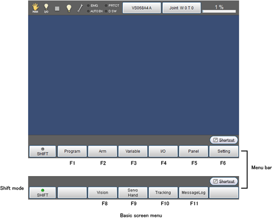
Each screen has its own command menu.In the command menu, press function keys to select command.
Basic Screen
Display the basic screen.Commands in the command menu can be sequentially reached from this basic screen.

The language selection screen is displayed when turning on the controller for the first time.
For details about the way of setting, refer to "Turning ON Robot Controller".
Icons
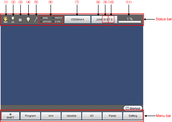
For details of icons displayed in the status bar on the basic screen, refer to the following list.

| № | Name | Description | |
|---|---|---|---|
| (1) | Move mode |  |
Auto mode |
 |
Manual mode | ||
 |
Teach check mode | ||
 |
Mode is not selected | ||
 |
Direct mode | ||
 |
Transmitting to PC | ||
 |
Receiving from PC | ||
 |
Write data into USB memory | ||
 |
Read data in USB memory | ||
 |
VirtualTP/RemoteTP is connected. | ||
| (2) | Executable token |  |
Arbitrary |
 |
COM | ||
 |
EtherNet | ||
 |
I/O | ||
 |
TP | ||
| (3) | Program running |  |
Program is under suspension. |
 |
Program is executing | ||
 |
Supervisory task is executing | ||
 |
Program and supervisory task are executing | ||
 |
Message output (Display when PrintMsg command execution) | ||
 |
Vicinity of the singular point (Sound the warning alarm when in the vicinity of the singular point) | ||
| (4) | I/O status/Arm status *Tapping each icon will display the detailed information of the icon. |
 |
Pseudo input unused and I/O lock unused (Note)I/O lock:Limit I/O communication with external devices |
 |
Pseudo input used or I/O locked | ||
At least, one of the followings is enabled. ・Virtual Fence |
|||
| (5) | System state |  |
Normal |
 |
Abnormal •Battery warning •Encoder system is down •Catastrophic failure (Level 5 error occurred) |
||
| (6) | Switch input state | EMG | Emergency stop state |
| AUTOEN | Auto enable state | ||
| PROTECT | Protective stop state | ||
| DSW | Deadman switch state | ||
| (7) | Robot selection button | Select and display the robot type | |
| (8) | Move mode | J : Each axis P : X-Y mode is displayed T : Tool |
|
| (9) | Work coordinate | Display the selected work number. | |
| (10) | Tool coordinate | Display the selected tool number. | |
| (11) | Velocity button | Setting and display of the external speed. | |
ID : 1692

