
ID : 4457
Arm Modeling
This window is for adding tools, work pieces, obstacles, and other objects to the equipment layout in the Arm 3D view window using 3D data from either the built-in simple modeling software or external sources.
Description of the Drop-down Menu
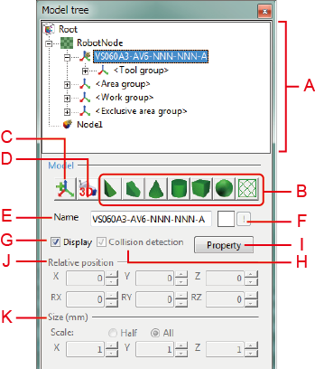
A: Object Tree
This shows the object hierarchy behind the Arm 3D view.
Right-clicking anywhere in the object tree area displays the following context menu.
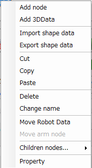
Add node
This is for adding a node underneath the selected object.
Add 3D data
This is for adding an object using 3D data from an external source.
Import shape data
This is for reading in existing modeling data.
Export shape data
This is for saving the modeling data for the selected node or object as a file.
Cut
This cuts the selected object and then paste it to the Windows clipboard.
Copy
This copies the selected object to the Windows clipboard.
Paste
This inserts the object in the Windows clipboard as a child of the currently selected object.
Delete
This deletes the selected nodes and objects.
Change name
This is for changing the name of the selected node or object.
Move Robot Data
The robot data moves as a child of the selected node or object.
This is for moving all data of Robot Nodes including the robot on the object tree.
Move arm node
The arm moves as a child of the selected node or object.
Children nodes...
All objects below the selected node can be expanded/collapsed, displayed / not displayed, interference checked / not checked.
Property
This displays the property sheets for the selected object.
B: Add Buttons
These add an objectof the shape indicated on the button. There are seven shapes available.
C: Node Button
This adds a node.
D: External Button
This reads in 3D data from an external source.
E: Name
This field specifies a name of the selected object.
F: Color
This field specifies a color of the currently selected object.
G: Display Check Box
Selecting this check box displays the currently selected object in the Arm 3D view.
H: Collision Detection Check Box
Selecting this enables collision detection for the currently selected object.
I: Properties Button
Pressing this button will display Model setting dialog box that configures properties of a model selected in the object tree.
J: Relative Position
These fields specify the relative position for the currently selected object.
- X, Y, Z
Relative x/y/z coordinates in mm. - RX, RY, RZ
Angles relative to the corresponding axis, in degrees.
K: Size
These fields specify the dimensions for the object selected in the tree.
- X, Y, Z
Dimensions along the x-, y-, and z-axes, in mm.
The radio buttons above offer a choice of specifying half- or full-sized measurements.
- If the data of the selected object is 3D data imported, the Size fields specify the magnification. Assuming the original size of the 3D data as "1," specify the magnification.
- Imported 3D objects cannot be edited.
- Entering negative values into the Size fields inverts the object.
ID : 4457