
ID : 38
Precautions When Designing End-effectors
The following specifications of an end-effector should not exceed those of the robot unit (refer to "Robot Specifications").
- Maximum payload
- Allowable moment of inertia (kgm2)
- Allowable moment (Nm)
An end-effector (including workpiece) should not vibrate.
In calculation for an end-effector design, take into account not only an end-effector but also all loads to be applied to the flange such as workpieces, wiring and piping.
If the end-effector design requirements are not met, the clamped sections of the robot unit may become loose, rattle or get out of position. In the worst case, the mechanical parts of the robot and the controller may become damaged.
A continuous fine, low speed motion may cause an overload error.
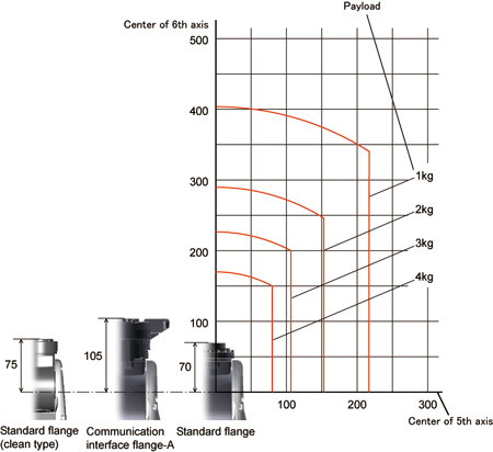
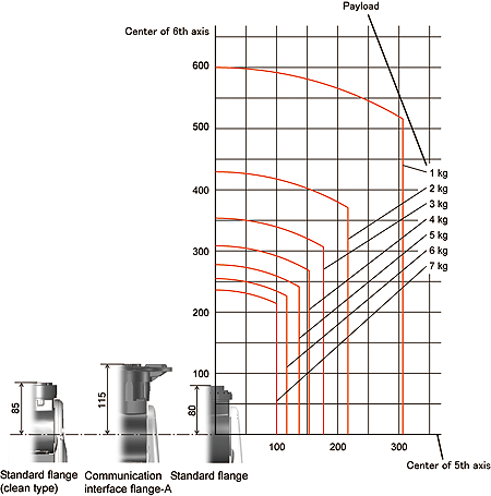
The graph below shows the distribution of the center of gravity position of an end-effector (including workpiece) whose volume is relatively small. Referring to the graph, design an end-effector.
VS-050 / 060
VS-068 / 087
When calculating moment of inertia around J4, J5 and J6 of a designed end-effector, refer to Section "Sample Calculation in Designing End-Effectors".
Precautions on End-effector installation
Do not apply any external force (such as hammering) on the datum hole φ5H7. Doing so will damage the hole. The diagram of "datum hole" is added.
For the datum hole, refer to "6th-Axis CALSET Position (Standard Type Robot, Standard Flange) ", "6th-Axis CALSET Position (Communication Interface Flange-A) ", or "6th-Axis CALSET Position (Dust- & Splash-proof Type and Protected Type) ".
ID : 38