
ID : 60
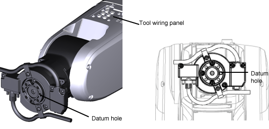
6th-Axis CALSET Position (Communication Interface Flange-A)
For robots equipped with a communication interface flange-A, determine the 6th-axis CALSET position using a dedicated CALSET pin. The 6th axis is not a boundless rotation joint, so checking secure rotations of the axis is necessary.
To setup, follow the process below.
CALSET Jig Assembly
1
Remove the CALSET pin for the communication interface flange-A.
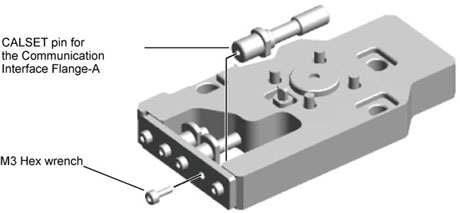
2
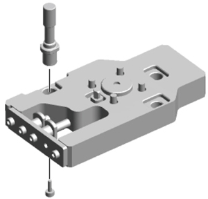
Mount the CALSET pin to the place drawing below indicates.
Tightening Torque: 2.0 +/- 0.4 Nm
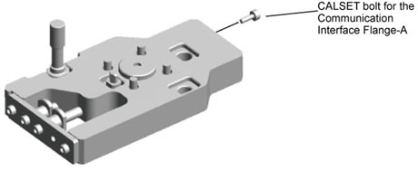
3
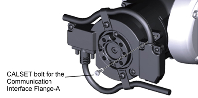
Remove the CALSET bolt for the communication interface flange-A
CALSET Jig Installation
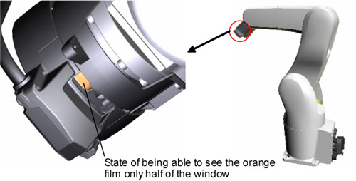
1
Turn the 6th axis until being able to see the orange film from a half of the window next to the flange. In case of not being able to see the orange film from the window next to the flange at all, turn the 6th axis to the negative direction (clockwise from the front of the flange). In case of being able to see the orange film from the entire window, turn the 6th axis to the positive direction (anti-clockwise).
2
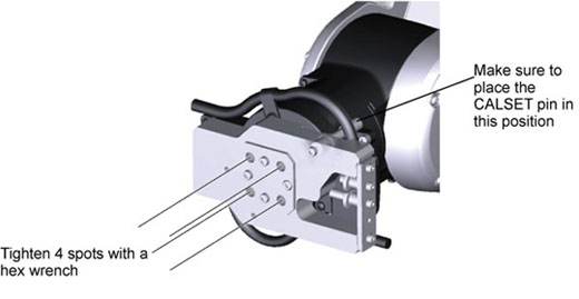
Set the 6 axis to the place drawing below indicates. (Near the 0 degree)
3
Mount the CALSET bolt for the communication interface flange-A.
Tightening Torque; 0.8+/-0.1Nm
4
Mount the CALSET jig.
Tightening Torque:8.8 +/- 1.7 Nm
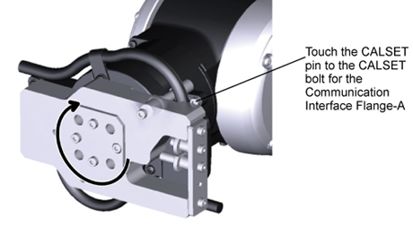
Positioning
Rotate the CALSET jig clockwise, touch the CALSET pin to the CALSET bolt for communication cable flange specification for A slightly.
ID : 60