
ID : 785
About Calculation of Edge Load Inertia
This is a calculation example for having inertia (moment of inertia) of edge load.
If you use your CAD for designing a gripper, use it for calculating the value.
Edge load is a combination of an end effector like a gripper for robot flange and a work.
Calculation of edge load inertia will be used at the cases as follows.
- You should not put edge load beyond the "maximum allowable inertia" in the specification of the robot.
- Inputting a condition of edge load into use condition parameter within a project will make "Gravity Compensation Control Function (GrvCtrl)" and "Optimum Speed Control Function (SpeedMode)" motions more smooth. * Attention
The unit of "maximum allowable inertia" in the specification of the robot is "kgm²."
The unit of edge load inertia at use condition parameter is "kgcm²."
Calculation should be done as to the condition.
Calculation Formula of Inertia (Moment of Inertia)
There are basic calculation formulas of inertia for each figure (cylinder1, cylinder2, cuboid, sphere, position of gravity center is not on rotation axis.
- l : Inertia (rotation moment)
- m : Mass
- r : Radius
- a, b, c, L : Length
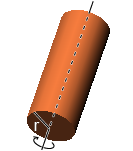
Cylinder1 (Rotate Around Central Axis of Circle)
Central axis of the circle is the rotation center.
Formula l = 1/2 * m * r^2
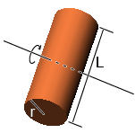
Cylinder2 (Rotate Around the Axis which is Perpendicular to the Central Axis of Circle)
Rotation axis is across the gravity center.
Formula l = 1/4 * m * ( r^2 + 1/3 * L^2)
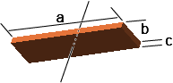
Cuboid
Rotation axis is across the gravity center.
Formula l = 1/12 * m * ( a^2 + b^2 )
Sphere
Rotation axis is across the gravity center.
Formula l = 2/5 * m * r^2

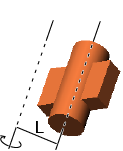
When the Position of Gravity Center is not on the Rotation Axis
lg:Inertia around gravity center
Formula l = lg + m * L^2
Example of Calculation of Inertia Around J4/J5/J6
We use the following end effector for the example.
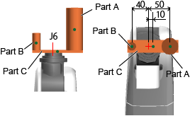
- PartA
- Radius (ra):20, Length (la):100, Mass (ma):1.0, Length from the rotation axis to gravity center (La)
- PartB
- Radius (rb):10, Length (lb):40, Mass (mb):0.1, Length from the rotation axis to gravity center (Lb)
- PartC
- Length (hc):120, Width (wc):15, Thickness (tc):10, Mass (mc):0.14, Length from the rotation axis to gravity center (Lc)
Inertia Around J6 (Ij6)
Inertia around J6 at PartA is
Ia6 = 1/2 * ma * ra^2 + ma * La^2
Inertia around J6 at PartB is
Ib6 = 1/2 * mb * rb^2 + mb * Lb^2
Inertia around J6 at PartC is
Ic6 = 1/12 * mc * (hc^2 + wc^2) + mc * Lc^2
Inertia around J6 at entire gripper is
Ij6 = Ia6 + Ib6 + Ic6
Inertia Around J5 (Ij5)
As to the length from the rotation axis of each part to gravity center, refer to the drawing of the robot for calculation. As to the inertia around J5 and J4, the length from gravity center depends on the axis position below the relevant axis. Calculation should be done using the position with maximum length.
Inertia around J5 at PartA should be the rotation axis which is perpendicular to the central axis of the cylinder.
Ia5 = 1/4 * ma * (ra^2 + 1/3 * la^2) + ma * La^2
Inertia around J5 at PartB should be the rotation axis which is perpendicular to the central axix of the cylinder.
Ib5 = 1/4 * mb * (rb^2 + 1/3 * lb^2) + mb * Lb^2
Inertia around J5 at PartC is
Ic5 = 1/12 * mc * (wc^2 + tc^2) + mc * Lc^2
Inertia around J5 at entire gripper is
Ij5 = Ia5 + Ib5 + Ic5
Inertia Around J4 (Ij4)
J4 will be calculated similar to J5's case.
ID : 785