ID : 3424
Signal Lines, Guides, and Wires
1
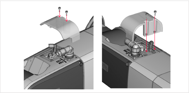
Attach the cover to protect the end-effector signal lines and pipe connector to the robot's second arm.
When using the signal line connector CN21 or the robot's built-in valve on the second arm, install an air pipe joint or dedicated connector before attaching the protective cover to prevent the robot jacket from being rubbed against the protrusions.
For details on the signal lines and connectors, refer to "Signal Lines & Air Piping·" in the robot manual.
The bolt size and tightening torque are as follows:
- Mounting bolt size: M3x8 mm
- Screw tightening torque: 1.6 Nm +/-20%

Even when the connector CN21 or the robot's built-in valve is not used, attach the protective cover to prevent the robot jacket from being rubbed against the protrusions.
2
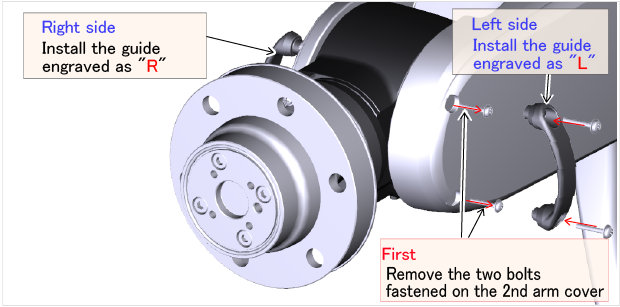
Install the guides to protect wiring and piping on the second arm of the robot unit.
To install the guides, remove the cross screws fastened on the second arm cover.
After removing the screws, fix the end-effector signal line and air piping guides with the accompanied cross screws (M3x16 size) as shown in the figure below.
Install the guide engraved as "R" on the right side and the guide engraved as "L" on the left side viewed from the robot.
The bolt size and tightening torque are as follows:
- Mounting bolt size: M3x16 mm
- Screw tightening torque: 0.59 Nm +/-20%

Even when wiring and piping are not used, be sure to install the guides to prevent the robot jacket from being rubbed against the bolt protrusions.
3
Install the appropriate cable ground on the jacket flange according to the signal line and piping to be used as shown in the table below.
Fill an unused cable ground hole with a seal plug.

For the cable ground types and conditions, refer to the following table.
| Condition | Wiring and piping are used | Wiring and piping are not used | ||
|---|---|---|---|---|
| Type | Wiring and piping diameter |
Wiring and piping diameter |
Normal | Thin head (*1) |
| Part number | Cable ground 1 410887-027* |
Cable ground 2 410887-026* |
Cable ground 1 410887-027*& seal plug 1 410915-021* or cable ground 2 410887-026*& seal plug 2 410915-020* |
410915-023* |
| Seal inner diameter | φ8 | φ5 | - | - |
| Cable ground main unit (tightening torque) |
1.0 - 1.5 Nm | 19.2 Nm +/-10% | ||
| Seal nut (tightening torque) |
0.8 - 1.2 Nm | - | ||
| Appearance color | Black | Silver | ||
(*1) To prevent interference from the end-effector caused by a normal seal plug, select a thin head seal plug instead.
- Select a cable ground with an inner diameter appropriate for the lines to be used. Check the inner diameter according to the seal inner part shown in the figure below.
- Wipe grease off fully before installing the cable ground.
- A nut is tightened on the washer of the cable ground, but remove it according to the image below as it is not used in this product. The nut can be removed by turning.

4
Put the signal lines and pipes through the cable ground and fix them by tightening the seal nut of the cable ground.
Before attaching the end-effector signal line connector to the cables, put the cables through the cable ground.

- Adjust the length of the signal lines and pipes according to your workable space.
- To maximize the workable space, a wiring length of 350 mm or more is required between the connector (pipe joint) and the cable ground seal.
ID : 3424

