
ID : 5551
I/O Allocation
Combination of I/O Extension Boards and Allocation Mode
For one robot controller, up to two extension boards can be installed. However, if you install two extension boards, the combination of board must be one PCI board and one PCI-Express board.
For about available combination of I/O extension boards and I/O allocation modes, refer to Combination of I/O Extension Boards and Allocation Mode.
I/O Allocation
The following table shows the port number of DeviceNet master board. For about I/O areas of the robot controller, refer to I/O Port Map and Allocation.
| Area | Number of points | I/O port No. |
|---|---|---|
| Input | 1024 points | 1024~2047 |
| Output | 1024 points | 2048~3071 |
When you set from the PC, you can allocate the score 1024 but you cannot allocate the score over 1024.
Node Address
The area of the DeviceNet Master input and output with the RC8 series robot controller are occupied ascending orders with the Node address registered the slave device.
Limitation of I/O Point per Node
There is no limitation of I/O point for both input and output per node. Make sure to allocate 8 points for one node.
Slave Status
RC8 series robot controllers do not use this information. Do not read it.
Slave status is added at the end of the input points automatically that are allocated by node. 192 points can be added at the maximum. If the number of points exceeds the DeviceNet Master input areas, which has 1024 points, the exceeded points are not displayed.
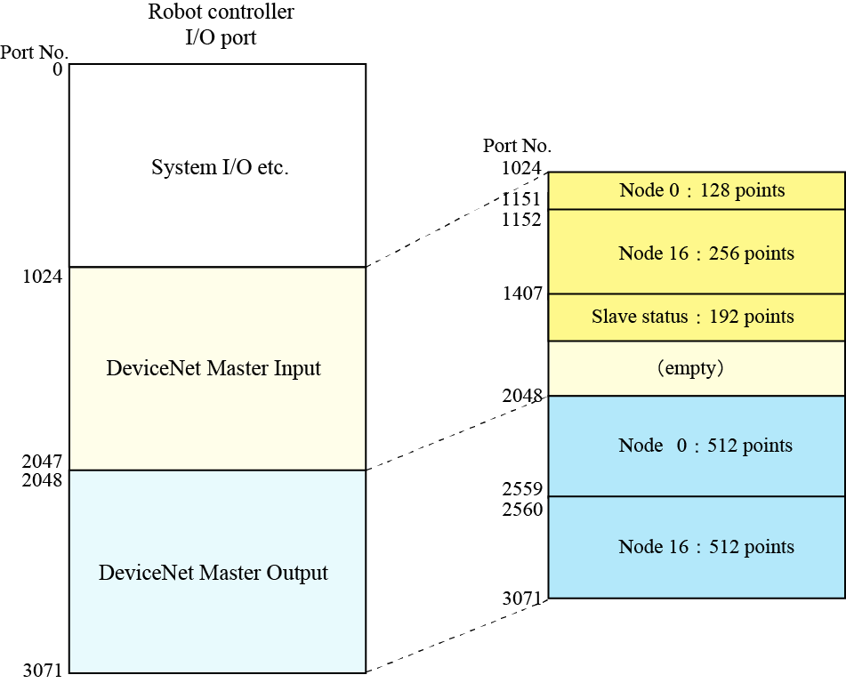
I/O Allocation Example
Assume that two slave devices, node 0 and node 16, are connected.
| Node address | Area | Points | I/O port No. |
|---|---|---|---|
| Node 0 | Input | 128 points | 1024~1151 |
| Output | 512 points | 2048~2559 | |
| Node 16 | Input | 256 points | 1152~1407 |
| Output | 512 points | 2560~3071 |
I/O Port Map Sample
|
ID : 5551
- Related Information
- I/O Size Setting for Slave Device