
ID : 6064
Setting the Control Set of Motion Optimization
The optimum speed or acceleration will vary depending upon the payload and center of gravity of an end-effector or workpiece that is to be set at the end of the robot flange. Set the payload and center of gravity position of the end-effector or workpiece and the control set of motion optimization according to the payload and robot posture.
For details, refer to the FUNCTION GUIDE, "Optimal Speed Control Function ".
For the operating procedure, refer to the FUNCTION GUIDE, "Setting the Load Conditions ".
The mass of payload is a total mass of an end-effector and workpiece, expressed in grams.
Define the payload center of gravity in the TOOL0 coordinates in units of mm.
6Axis Robots
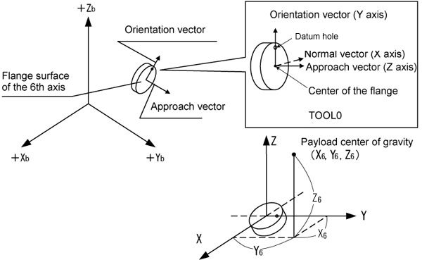
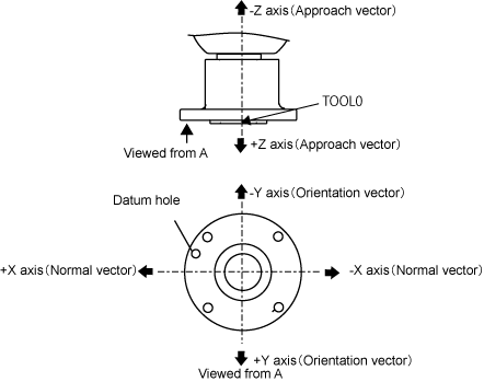
TOOL 0 coordinates of the 6axis robot is defined as the illustration below.
The origin of the TOOL0 coordinates is located in the center of the flange surface on the 6th axis.
The Y component is defined on the orientation vector directed from the center of the flange to the center of the datum hole. The Z component is defined on the approach vector directed from the center of the flange to the normal line of the flange center. The X component is defined on the normal vector directed along the X axis (+) in the right-hand coordinates whose Y axis is an orientation vector and whose Z axis is an approach vector.
Datum hole is a pin hole which exists on the flange surface.
The size of datum hole differs depending on the robot types; φ6H7 for VM series, φ5H7 for other robots.
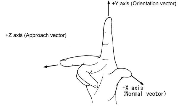
Right Hand Coordinate System
4-Axis Robots
TOOL 0 coordinates of the 4axis robot is defined as the illustration below.
The origin of the TOOL0 coordinates is located in the center of the flange surface on the 4th axis.
ID : 6064