
ID : 882
Examples of Changing the Mechanical Ends by Mechanical Stoppers
|
Explanation of changing the 2nd-axis mechanical ends
|
||
|
Fixing position of mechanical stopper |
Mechanical end positions |
|
|---|---|---|
| Positive direction (+) | Negative direction (-) | |
| Original |
A0 <Original mechanical end position> +137° 13' <Original software motion limit> +135° |
B0 <Original mechanical end position> -92° 13' <Original software motion limit> -90° |
| 1 |
A1 (25° inside from A0) |
- |
| 2 |
A2 (55° inside from A0) |
- |
| 3 |
A3 (85° inside from A0) |
- |
| 4 |
A4 (115° inside from A0) |
- |
| 5 |
- |
B4 (115° inside from B0) |
| 6 |
- |
B3 (85° inside from B0) |
| 7 |
- |
B2 (55° inside from B0) |
| 8 |
- |
B1 (25° inside from B0) |
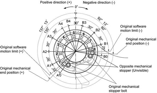
Note: The software motion limits should be 2° to 3° inside the new mechanical end positions.
ID : 882