
ID : 1038
Program No. Select (Input)
Function
The program number to be executed can be specified from the external device by inputting this signal.
Input Conditions and Operation
- This signal is executable only in the external mode. In other modes, an error will be displayed, and the terminal motor power will be turned OFF.
- As shown in the table given on the next page, the program No. select signal is made up of eight bits of 20 to 26 and the parity bit.
- Input a decimal program number by converting it into binary 20 to 26 and parity bit.
- "Short" represents the bit value = 1, "open" represents the bit value = 0, and the parity bit is odd parity.
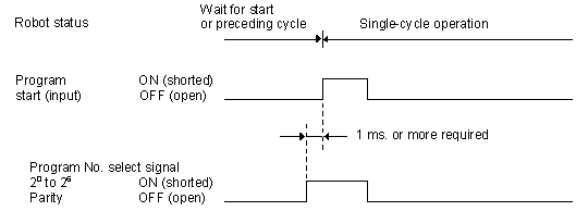
- As shown below "Timing chart", input the program No. select signal before the program start signal (1 msec. or more), and hold the state until the robot starts to operate. If this condition is not met, an error will be displayed, the power to the motor will be turned OFF.
-
Input 1 or 0 as the parity bit so that the total of 1's existing in the eight bits of 20 to 26 and the parity bit will be odd.
Example: When the program number is 15, the bit status of 20 to 26 is (001111), and the total number of 1s is four, an even number. Set 1 as the parity bit to make the total number of 1s five, an odd number.
- The bit value =1 represents short, and the bit value =0 represents open.
- The program numbers executable from the external device are limited to Program No. 0 to 127.
- Invalidation of the parity bit is not recommended.
Timing Chart
 |
Example of Program No. Select Signals
|
Input signal |
Program No. (decimal) |
|||||
| 1 | 15 | 26 | 65 | |||
| 20 | = | 1 | 1 | 1 | 0 | 1 |
| 21 | = | 2 | 0 | 1 | 1 | 0 |
| 22 | = | 4 | 0 | 1 | 0 | 0 |
| 23 | = | 8 | 0 | 1 | 1 | 0 |
| 24 | = | 16 | 0 | 0 | 1 | 0 |
| 25 | = | 32 | 0 | 0 | 0 | 0 |
| 26 | = | 64 | 0 | 0 | 0 | 1 |
|
Parity |
0 | 1 | 0 | 1 | ||
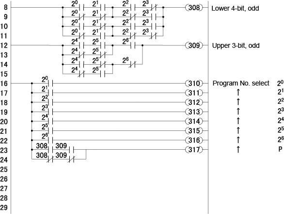
The figure below shows an example of a program No. select signal sequence circuit considering parity.
 |
ID : 1038