
ID : 2859
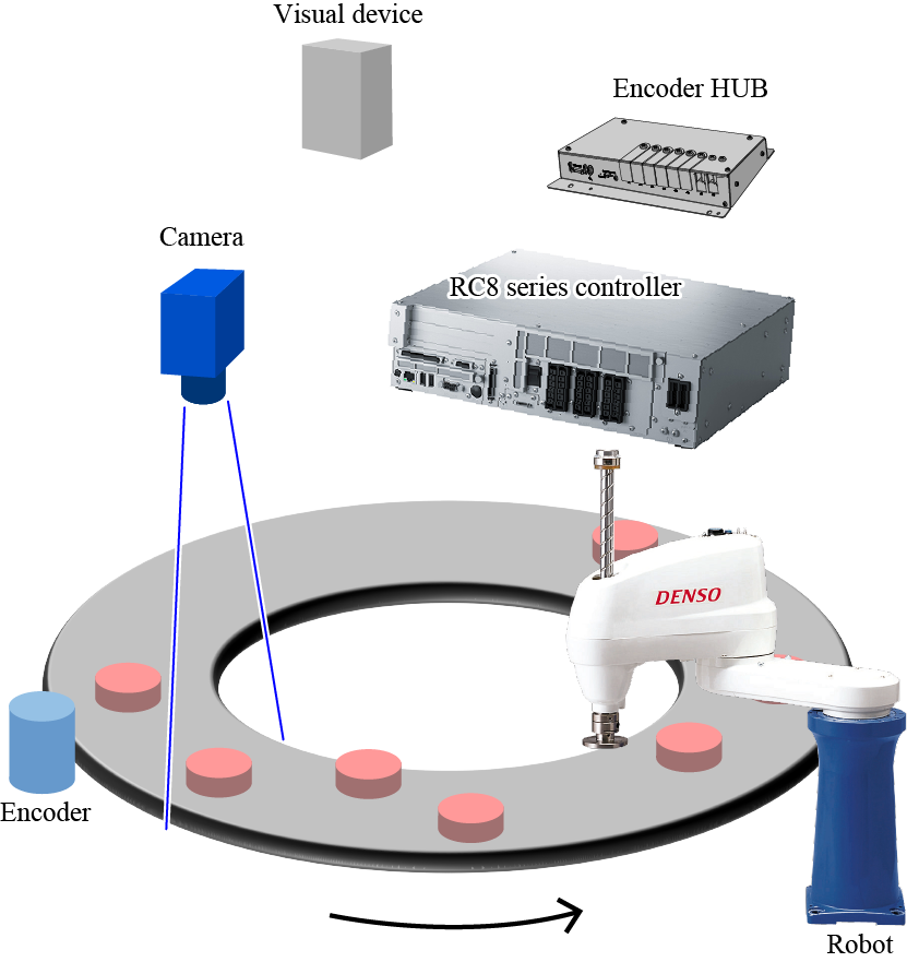
System Configuration of the Vision Tracking
Configuration of the vision tracking is illustrated below.
The vision tracking system is applied to pick up workpieces which are placed on arbitrary position on the moving turntable.
The system executes two different programs simultaneously; one is a program to recognize coordinates of a workpiece and the other is a program to pick it up.
A program which recognizes coordinates of workpieces operates as shown below.
Visual device starts recording once receiving an instruction from the controller. If workpiece exists, the visual device sends position data of workpiece to the controller.
Once the visual device starts recording, it transmits trigger signal to the controller, then the controller immediately obtains position data from the encoder.
The controller stores workpiece's position data transmitted from the visual device and position data obtained from encoder per workpiece.
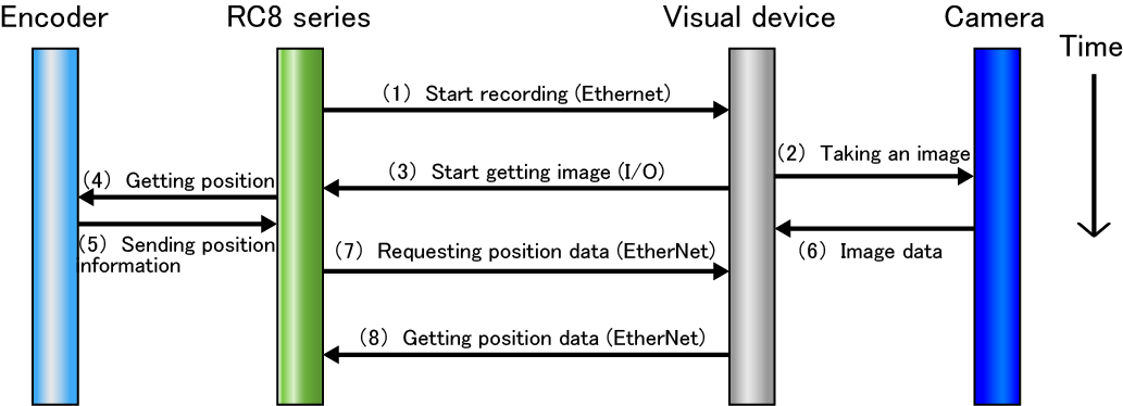
In a picking up program, the controller reads the stored position data of workpiece, then the robot picks up a workpiece by adjusting the robot arm in response to the workpiece's motion.
Wiring Diagram
Wiring diagram is illustrated below.
To connect to the encoder HUB, connect to the port according to the joint number of the encoder.

Encoder Hub
For encoder hub, there are old model and new model.
If you use a new model, connect the encoder line of the motor & encoder cable to the encoder hub's connector port indicated as "ROBOT-0" (on the left side viewed from the front).
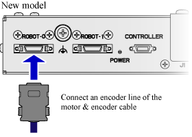
For details about the external diagram and the precaution on installation, refer to "Encoder HUB".
ID : 2859