
ID : 3405
Setup Procedure when Operating with Two Robots and N Lines of Conveyor (Each Robot Runs on Individual Conveyor)
Set each conveyor setting for Robot0 and Robot1, respectively.
In this example, the setup target system has the following conditions.
-
The following shows the conditions applied to the conveyor for Robot0.
- Connect the encoder to the 7th joint of the encoder hub.
- Use the conveyor number 1.
-
The following shows the conditions applied to the conveyor for Robot1.
- Connect the encoder to the 8th joint of the encoder hub.
- Use the conveyor number 2.
In actual setup, enter appropriate parameters according to the system you will setup.
The following describes the entire setup procedures.
| Process | Description |
|---|---|
| 1. Robot0 Setting |
|
| 2. Robot1 Setting |
|
Because of the number of conveyors used, the CPU performance of the robot controller could be insufficient, leading to lower performance. In this case, reduce the number of conveyors and distribute the load to additional controller so that CPU load on the robot controller is reduced. Or, consider the use of a high-spec CPU installed robot controller.
1. Robot0 Setting
1
Set the target robot of the teach pendant setting to Robot0.
Press the [Robot selection] button to display [Robot selection] window. From the [Robot selection] list, select [Robot0(R0)] and press the [OK] button.
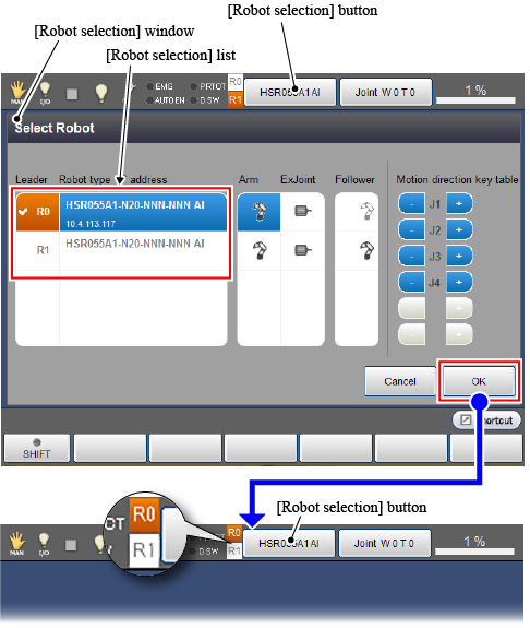
Check if an [R0] icon on the left of the [Robot selection] button turns orange. (See the above figure.)
2
Set an encoder-connected joint.
Set the user level to [Maintainer] and then follow the operation path below. [Motor Setting] window appears.
Operation path : [F2 Arm] - [F12 Maintenance] - [F10 Joint Settings] - [F6 Motor Setting] |
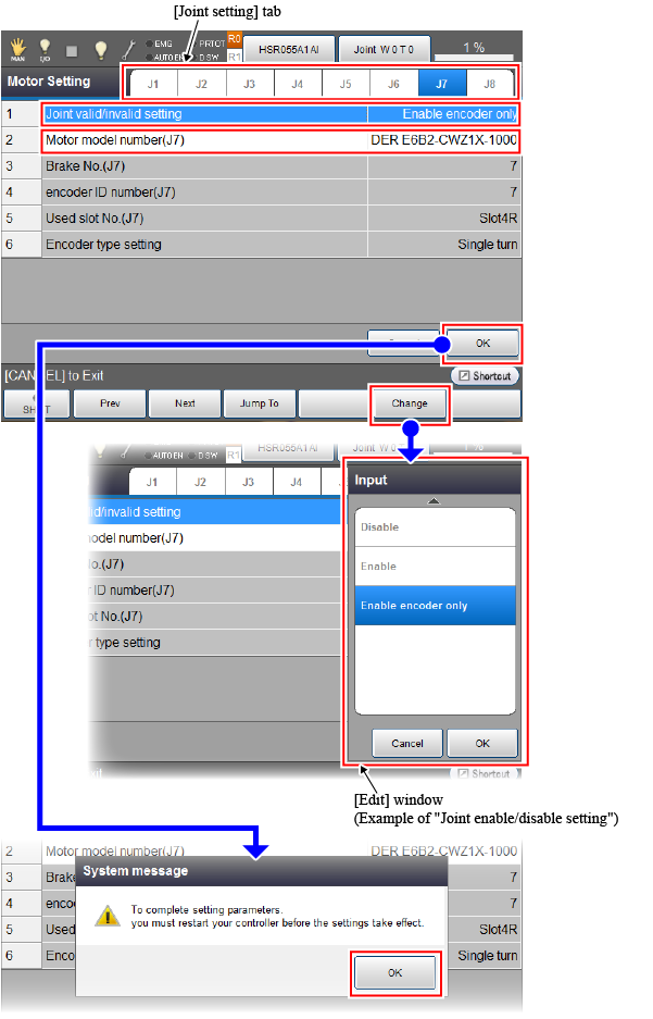
From the [Joint setting] tab, select a joint number.(For example, select "J7" for the 7th joint) When the motor setting parameter of the 7th joint is displayed, set each parameter as the following table shows.
|
Setting parameter (Number : Parameter name) |
Setting value |
|---|---|
| 1 : Joint enable/disable setting | Enable encoder only |
| 2 : Motor model number (J7) | ENCODER E6B2-CWZ1X-1000 |
Place the cursor on the parameter to set, and press [F5 Change]. Once the [Edit] window appears, select a value and then press [OK] button.
After all parameters have been set, press the [OK] button on the [Motor Setting] window. Once the system message of parameter setting completion appears, press [OK].
Before turning off the robot controller, check the following items.
- Check that the "Joint enable/disable setting" of the 8th joint of Robot0 is set to "Disable".
- Check that the "Joint enable/disable setting" of the 7th joint of Robot1 is set to "Disable".
To check the [Joint enable/disable setting] of Robot1, press the [Robot selection] button and set the teach pendant setting target robot to [Robot1]. With referring to the above operation, display the [Motor Setting] window, check the motor setting of the 8th joint.
3
Reboot the robot controller.
Turn off the robot controller and turn on the controller again.
Once the robot controller start up, set the teaching pendant setting target robot to Robot0.
4
Set Robot0 as a master.
Set the user level to [Maintainer] and then follow the operation path below. [Tracking] window appears.
Operation path : [F10 Tracking] |
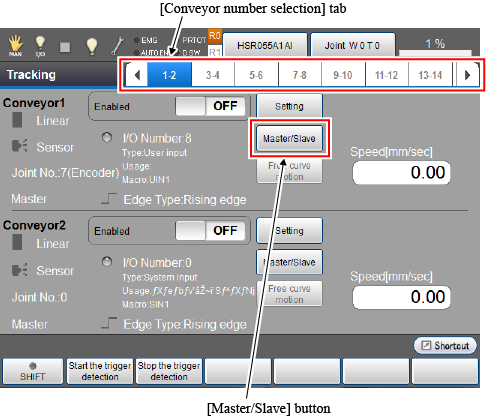
From the [Conveyor number selection] tab, select the [1-2] cell that indicates the conveyor number 1 and 2. Press the [Master/Slave] button of the conveyor number 1 to display the following [Master/Slave selection] window.
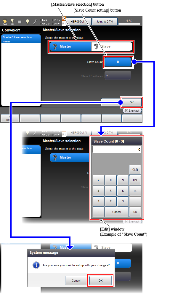
Set each parameter along with the following instructions.
| Items to set | Setting value / Setting method |
|---|---|
| Master/Slave selection |
Setting value : master |
|
How to set : Press [Master] of the [Master/Slave selection] button. ("Master" changes to blue.) |
|
| Slave Count |
Setting value : 0 |
|
How to set : Press the [Slave Count setting] button. On the [Edit] window, select "0". Press the [OK] button on the [Edit] window. |
After all setting items have been set, press the [OK] button on the [Master/Slave selection] window. Once the following system message appears, press [OK] to back to the [Tracking] window.
If you change the conveyor's state from Slave to Master, when you press the [OK] button on the [Master/Slave Selection] window, two system messages are displayed in sequence. For each system message, press [OK] to back to the [Tracking] window.
5
Execute the hardware setting for conveyor, connection confirmation, and conveyor-robot (Robot0) calibration. After that, execute the camera calibration.
The operation procedure is the same as that of only one robot-used system. Refer to "Selecting a Hardware", "Hardware Connection Confirmation", "Calibration", "Calibration Procedure for the Camera". However, be sure to keep the setting target robot of teach pendant as Robot0.
6
To use several conveyors, repeat the operation from STEP1 to STEP5 up to the number of conveyors.
2. Robot1 Setting
1
Set the target robot of the teach pendant setting to Robot1.
Press the [Robot selection] button to change the target robot. (Refer to "STEP1" on "1. Robot0 setting")
Check if the [R1] icon on the left of the [Robot selection] button turns orange. (See the figure below.)

2
Set an encoder-connected joint.
Set the user level to [Maintainer] and then follow the operation path below. [Motor Setting] window appears.
Operation path : [F2 Arm] - [F12 Maintenance] - [F10 Joint Settings] - [F6 Motor Setting] |
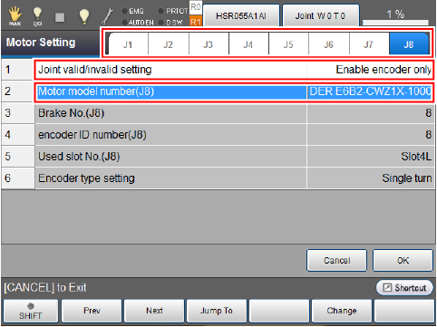
In Robot1, perform the 8th joint setting. Set each parameter along with the following instructions.
|
Setting parameter (Number : Parameter name) |
Setting value |
|---|---|
| 1 : Joint enable/disable setting | Enable encoder only |
| 2 : Motor model number (J8) | ENCODER E6B2-CWZ1X-1000 |
For about the setting method, refer to "STEP2" of "1. Robot0 setting".
3
Reboot the robot controller.
Turn off the robot controller and turn on the controller again.
Once the robot controller start up, set the teaching pendant setting target robot to Robot1.
4
Set Robot1 as a master.
Set the user level to [Maintainer] and then follow the operation path below. [Tracking] window appears.
Operation path : [F10 Tracking] |
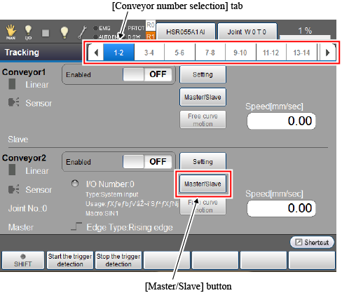
From the [Conveyor number selection] tab, select the [1-2] cell that indicates the conveyor number 1 and 2. Press the [Master/Slave] button of the conveyor number 2 to display the [Master/Slave selection] window.
The setting items and operations are the same as Robot0. Set necessary parameters with referring to "STEP4" of "1. Robot0 setting".
5
Execute the hardware setting for conveyor, connection confirmation, and conveyor-robot (Robot1) calibration. After that, execute the camera calibration.
The operation procedure is the same as that of only one robot-used system. Refer to "Selecting a Hardware", "Hardware Connection Confirmation", "Calibration", "Calibration Procedure for the Camera". However, be sure to keep the setting target robot of teach pendant as Robot1. Also, the setting target conveyor must be the conveyor which is set as conveyor number 2.
6
To use several conveyors, repeat the operation from STEP1 to STEP5 up to the number of conveyors.
ID : 3405