
ID : 6127
Wire Connection Required in Starting Up the Robot
This section shows the minimum wire connection required for the stand-alone robot unit to turn the motor power ON or run in Auto or Manual mode during adjustment in starting up the robot system.
Configuration of Safety Circuit
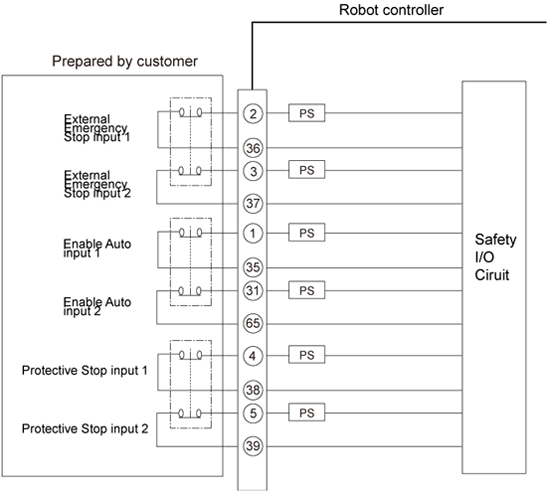
Input signals to the safety circuit are important for safety. Be sure to configure their circuits with contacts as shown below, observing the notes given below.
 |
For the overall configuration of safety circuits, refer to Mini I/O MANUAL for respective controllers.
RC8A : [NPN type] Safety Circuit of RC8A, [PNP type] Safety Circuit of RC8A
RC8 : [NPN type] Safety Circuit of RC8, [PNP type] Safety Circuit of RC8
Wire Connection Required for Motor ON
Short-circuiting both the Emergency Stop input circuits (dual line) only enables the motor to turn ON.
| Input signal name | Terminal number |
|---|---|
| External Emergency Stop 1 | #2 and #36 on Mini I/O connector |
| External Emergency Stop 2 | #3 and #37 on Mini I/O connector |
Two External Emergency Stop input signals must be controlled with separate contacts. Two circuits connected in parallel using a single contact or an always-shorted circuit will be interpreted as an external circuit failure so that the emergency stop state cannot be reset.
Wire Connection Required for Automatic Operation
Turning this signal ON (shorting) enables switching to Auto mode.
| Input signal name | Terminal number |
|---|---|
| Enable Auto 1 | #1 and #35 on Mini I/O connector |
| Enable Auto 2 | #31 and #65 on Mini I/O connector |
| Protective Stop 1 | #4 and #38 on Mini I/O connector |
| Protective Stop 2 | #5 and #39 on Mini I/O connector |
- Two Enable Auto and two Protective Stop input signals must be controlled with separate contacts. Two circuits connected in parallel using a single contact or an always-shorted circuit will be interpreted as an external circuit failure so that the circuit will not operate.
- If no Protective Stop input signals are needed, their circuits can be always short-circuited by terminal connection with jumpers between #4 and #38 and between terminals #5 and #39 on Mini I/O connector.
ID : 6127