
ID : 4011
COBOTTA Unit
This section describes the following information on installation of the COBOTTA unit.
- Environmental conditions of installation position
- Dimensions of screw holes for fixing
- Force applied to the workbench for fixing
- Clearances required around COBOTTA
- Changing method of the motion range
Environmental Conditions of Installation Site
Install COBOTTA in an environment that meets the following conditions:
| In storage/ In transportation | In operation | |
|---|---|---|
| Ambient temperature | -10℃ to 60℃ | 0℃ to 40℃ |
| Relative humidity | 20% RH to 80% RH (no dew condensation allowed) | |
| Vibration | 29.4 m/s²(3 G) or less | 4.9 m/s²(0.5 G) or less |
| Altitude | -- | 1,000 m or less |
| Levelness | 0.5° | |
| Flatness of installation surface | 0.1/500 mm | |
| Defacement (pollution) degree (*1) | 2 | |
| Over-voltage category (*2) | II | |
|
Where COBOTTA cannot be installed |
|
|
*1: Pollution degree 2 is equivalent to household and office environment.
*2: Overvoltage category II refers to energy consuming equipment to be supplied from fixed installation (such as outlet).
Dimensions of Screw Holes for Fixing
On the workbench for fixing, open screw holes and install dowel pins as shown below.
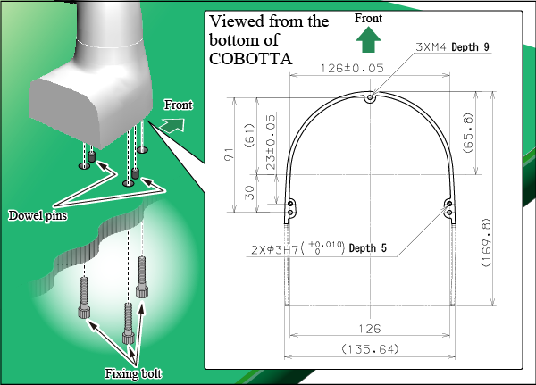
Prepare fixing screws having the following specifications. Tighten them with the following tightening torque.
| Specifications |
|
|---|---|
| Tightening torque |
2.9 Nm ±20% |
Force Applied to the Workbench for Fixing
Force applied to the workbench for fixing is categorized in four types as shown in the following figures.
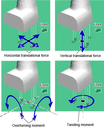
The maximum value of each type of force varies depending on the setting of speed limit of COBOTTA. The following table shows maximum values of each type of force against values of speed limit.
The workbench for fixing COBOTTA should provide the strength to withstand the force shown in the table below.
| Type of force | Value of speed limit | |
|---|---|---|
| If set to default value | If set to maximum value | |
| Horizontal translational force | 4.3 N | 26.6 N |
| Vertical translational force | 104.2 N | 108.0 N |
| Overturning moment | 17.9 Nm | 25.5 Nm |
| Twisting moment | 1.4 Nm | 4.4 Nm |
- Joining the workbench for fixing to any other very heavy installation can increase the strength of the workbench.
- During operation of COBOTTA, the workbench may generate resonance noise (howling). If so, increase the strength of the workbench or slow down the operation of COBOTTA.
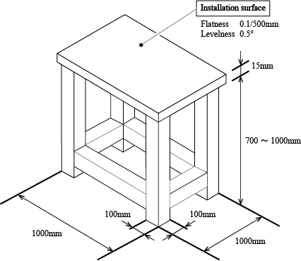
Example of Workbench
The following figure shows a sample diagram of a workbench.
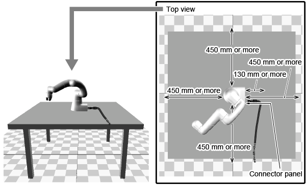
Clearances Required Around COBOTTA
- Provide a clearance of 450 mm or more between the edge of the fixing workbench and the edge of installed COBOTTA for safety reason.
- Provide a clearance of 130 mm or more near the connector panel because various cables are connected to it (This clearance is called "cabling space").
Changing method of the motion range
You can change the motion range of COBOTTA if necessary.
To change the motion range, use software (Mechanical stoppers are not used).
For changing methods by software, there are the following two types.
- Change the software limit.
- Change the limit values of the axis limit function (the limit values of SAL).
When changing the motion range, please be sure to perform both of the above two methods. Do not change only the software limit or the axis limit function. Be sure to change both of them.
To change the above two, use COBOTTA parameter tool.
For the operation procedure of COBOTTA parameter tool, refer to "COBOTTA Parameter Tool Guide".
ID : 4011