
ID : 7147
Precautions while Robot is Running
- COBOTTA is designed for users who are 16 years-old or older.
- When using COBOTTA, the upper half of the human body (fingers, hands, arms, chest, shoulder, back, abdomen, and pelvis) is more likely to contact to COBOTTA.
A "work" as is defined in this section includes all operations such as transportation, installation, assembling the robot facilities, (electric wiring, mounting tool or end-effecter, air piping) adjustment, anomalous correspondence procedure in case of abnormal situations, maintenance, cleaning.
Also, workers are classified into categories described in "Classification of Users". Each user must take a training described in "Classification of Users".
Installing Protective Equipment
- Workers shall wear protective equipment, such as hardhat, protective shoes, and protective glasses, according to the risk assessment.
- When treating grease, make sure to wear gloves and protective glasses to prevent the grease from adhering to skin and eyes.
Precautions for Operation
- Do not place your body under the robot during operation. If the result of application's risk assessment indicates the likelihood of contact with one's body, be sure to take necessary protective measures, such as wearing protective equipment, setting safety guards.
- Do not put one's head within the restricted space of robots.
- To avoid damage, do not apply strong force on the robot. Do not sit on or hang from the robot.
- Be careful so that clothes and hair are not to be entangled.
- If a brake is released, the robot arm may move by own weight. When you release a brake, be sure to support the robot to avoid falling.
- If workers operate within the restricted space, place an emergency switch close to workers so that they can immediately stop the robot in an emergency.
- A robot becomes hot during operation. If you contact a robot body when the environment temperature is high, you could get burned. Before you contact the robot for a long time for direct teaching or other reason, turn the power off and wait until the robot becomes cool.
Creation of Working Regulations and Assuring Worker Adherence
When entering the robot's restricted space to perform teaching or maintenance inspections, set "working regulations" for the following items and ensure workers adhere to them.
- Operating procedures required to run the robot.
- Robot speed when performing teaching.
- Signaling methods to be used when more than one worker is to perform work.
- Steps that must be taken by the worker in the event of a malfunction, according to the contents of the malfunction.
- The necessary steps for checking release and safety of the malfunction status, in order to restart the robot after robot movement has been stopped due to activation of the emergency stop device.
- Apart from the above, any steps below necessary to prevent danger from unexpected robot movement or malfunction of the robot.
- Display of the control panel.
- Assuring the safety of workers performing jobs within the robot's restricted space.
- Maintaining worker position and stance. Position and stance that enables the worker to confirm normal robot operation and to take immediate refuge if a malfunction occurs.
- Implementation of measures for noise prevention.
- Signaling methods for workers of related equipment.
- Types of malfunctions and how to distinguish them.
Please ensure "working regulations" are appropriate to the robot type, the place of installation and to the content of the work.
Be sure to consult the opinions of related workers, engineers at the equipment manufacturer and that of a labor safety consultant when creating these "working regulations".
Display of Operation Panel
To prevent anyone other than the worker from accessing the start switch or the changeover switch by accident during operation, display something to indicate it is in operation on the operation panel or tablet. Take any other steps as appropriate, such as locking the cover.
Safety Installation and Operation of the Hand (end-effector)
- When install or operate the hand and tool (end-effector), make sure that power loss, changes of air or power supply do not cause hazardous conditions. Also, please be aware that residual energy might exist inside the device.
- If the customer provides the optional finger of gripper, make sure that the finger has no sharp portion. To ensure the safety, be sure to perform the risk assessment. Also, when the customer prepares the entire gripper, be sure to perform the risk assessment. Based on the result of risk assessment, take necessary protective measures, such as to eliminate sharp portion and to limit the force to 140 N or lower.
- When you design, create, and mount a gripper or workpiece, make sure that the gripper or workpiece satisfies the specification conditions written in the user's manual. If not, the robot could cause damage to personnel or could damage the robot itself. In addition, the robot will be out-of-warranty.
- Note that an electric vacuum generator may become hot in continuous operation. When an operator touch an electric vacuum generator for replacement of vacuum pad or alike, wait until the generator is cool enough.
- Do not look into the air intake hole of an electric vacuum generator. Due to the blowing operation or others, dusts stacked in the filter of the electric vacuum generator may be blown off.
Camera
When the customer provides the camera to attach the arm, be sure to perform the risk assessment. Based on the result of risk assessment, take necessary protective measures, such as to eliminate sharp portions. Also, the customer needs to perform the calibration because the calibration data of the optional AF camera (N10-W02) cannot be used.
Parameter Setting for Speed Limit
- Speed limit parameters shall be determined by the risk assessment result.
- Before sending parameters, with a COBOTTA parameter tool, check if the all parameters are properly configured. For information about how to set a parameter, refer to "COBOTTA parameter tool user's guide"(PDF:2,639KB).
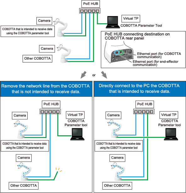
From the Help menu, select [User's guide] to open the user's guide.When sending COBOTTA parameter tool data to COBOTTA, make sure to connect the COBOTTA parameter tool and COBOTTA receiving the data on a one-to-one basis.
For example, if if two units of COBOTTA are connected using PoE HUB, as shown below, reconnect the units using either of the following methods.
- Remove the network line from the COBOTTA that is not intended to receive data.
- Directly connect to the PC the COBOTTA that is intended to receive data.
After sending COBOTTA parameter tool data with the above connections, make sure to restore the connections to its former state.
- After sending a parameter, always check that the robot moves as intended.
- To avoid an accident caused by the parameter change, keep your password strictly confidential.
Inspections Before Commencing Work
Before starting work, inspect the following items, carry out any repairs immediately upon detection of a malfunction and perform any other necessary measures.
- Check for any damage to the sheath or cover of the external wiring or to the external devices, check if there is no incorrect wiring connection.
- Check that the robot is functioning normally or not (any unusual noise or vibration during operation).
- Check the functioning of the emergency stop device.
- Check there is no leakage of air or oil from any pipes.
- Check there are no obstructive objects in or near the robot's restricted space.
- Place emergency switches close to workers so that they can press the switches immediately in an emergency.
- Personnel who are not engaged in the operation shall not stay in the restricted space.
- Fix the robot so that it does not drop or turn over.
Inspections Before Powered ON
To avoid electric shock or damage to the product, before turning on your COBOTTA, check that there is no damage to cables or wires.
Release of Residual Air Pressure
Before disassembling or replacing pneumatic parts, first release any residual air pressure in the drive cylinder.
Initial Test after Installation or Parts Replacement
After the installation, parts replacement, or the software version upgrade, perform the initial test.
Perform the following items for the initial test.
- Perform the same items as the annual inspection.
-
Check that all the safety-related functions work normally.
(Example : While a robot runs at low speed, press the push-button switch on the emergency stop box, and then check that the robot stops.)
- Check that all axes work normally in the manual operation.
If the robot passes all of the above check items, it passes the test.
Precautions for Test Runs
Whenever possible, have the worker stay outside of the robot's restricted space when performing test runs.
Perform initial test and periodical check-up to confirm whether the protective measure is effective. Protective measure includes emergency stop switches, protective stop signals, mechanical stoppers, and safety functions (SLS, SLT, and SAL).
Precautions for Diagnosis Motion
Do not enter the motion area of robot during diagnosis motion. Robots may perform unexpected behavior.
Precautions for CALSET
During the automatic CALSET positioning procedure, the robot may exhibit unexpected movements. Do not enter the motion range of the robot.
Precautions for Packing Posture Movement
In packing posture movement, unintended motion may occur. Do not enter the motion range of the robot.
Precautions for Program Start
- At start-up
Before starting a program, make sure that all safety functions and protective functions are working properly. Also, check the following points, set the signals and signs to be used, and perform the signaling practice with all related workers.
- Check that tools are in their designated places.
- Check that no lamps indicating a malfunction on the robot or related equipment are lit.
- Check that no one is around the robot.
- Steps to be taken when a malfunction occurs
Stop the robot's operation by activating the emergency stop device when it is necessary to enter the safeguarded space with a safety fence to perform emergency maintenance in the case of malfunction of the robots or related equipment.
Take any necessary steps such as posting a notice on the start switch to indicate work is in progress to prevent anyone from accessing the robot.
Precaution for Power Switch
- For safety purposes, make sure to shutdown the power supply to the COBOTTA by pulling off the power connector or turning off the customer-prepared breaker before maintenance, repair or parts replacement.
- A power switch of the COBOTTA is the second circuit breaker. Residual current exists inside of the COBOTTA after turn off the switch. In operation, be sure to disconnect the power connector or turn off the circuit breaker of the equipment to make sure that the power supply to the COBOTTA is shut off.
- Also, take other safety measures, such as pulling off the outlet plug so that other workers cannot power on the unit inadvertently.
- Do not use the power switch of the power tap as the breaker.
Precautions in Cleaning
Make sure to turn off the power breaker of the installation before cleaning of the robot, cables and other parts or disconnect the power connector.
Safety Storage of Tablet
To prevent misuse, please store unused tablet in a controlled area.
Precautions in Repairs
- Do not perform repairs outside of the designated range.
- Under no circumstances should the interlock mechanism be removed.
- When opening the COBOTTA's cover, always turn the COBOTTA off and disconnect the power cable.
- Use only spare tools specified in this manual.
Action During Emergencies and Malfunctions
Decide on actions to be taken by personnel when emergencies or malfunctions occur, and train them in advance.
In case a personnel's body part is trapped by COBOTTA,
- Release a brake with a tablet, and then escape. For how to release a brake, refer to Brake Setting.
- If a brake cannot be released, hold the arm and forcibly move it to escape.
To prevent injury, please be careful not to apply too much force when pressing the axis, especially for axis which does not equip the brake.
The following table shows the remaining lifetime of each brake when each axis is moved by 90°.
| Brake lifetime [number of times] | |
|---|---|
| 1st axis | 350 |
| 2nd axis | 100 |
| 3rd axis | 200 |
| 4th axis | 950 |
| 5th axis | 1,000 |
| 6th axis | - |
The 6th-axis does not equip a brake.
Mechanical Stoppers
If the robot collides against any mechanical stopper, the robot might be damaged. Check the following points before use.
As a result of the mechanical stopper condition check, if you find unintended robot motion, such as getting out of position, contact our service representative.
-
Check the mechanical stopper position
Release the brakes of the COBOTTA first, and then move the COBOTTA slowly until each axis reaches to the mechanical stopper. When you move the COBOTTA, be careful not to apply excessive force to the mechanical stoppers. For how to release a brake, refer to Brake Setting.
Once all axes reach to the mechanical ends, check if the angle gap between the mechanical stopper’s current angle value and the mechanical end reference value is within 5 degrees in each axis.
<Mechanical end reference value>
+ side - side 1st axis +152.5 -152.5 2nd axis +102.9 -62.9 3rd axis +142.1 -15.9 4th axis +172 -172 5th axis +141.2 -101.2 6th axis +173.5 -173.5 -
Check the taught point
Move the robot to the taught point. Check that the tool end position matches with the taught point.
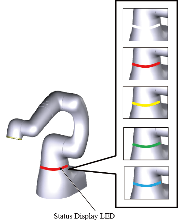
Status Display LED
COBOTTA unit equips an LED which displays a status of itself on its body. There are two types of LED blink speed: slow blinks and fast blinks. Whenever COBOTTA is in the startup state, LEDs will light up or blink in the designated color.
When in fast blink, the LED repeats turning on and off at 360-millisecond interval.
When in slow blink, the LED repeats turning on and off at 1440-millisecond interval.
For the way of displaying an LED corresponding to COBOTTA status, refer to "Way of displaying LED and COBOTTA status” described below.
- If the LED does not light up or does not fully light up in the designated color, the LED may be malfunctioning. Stop the robot immediately and contact our service representative.
- The LED plays an important role to check the COBOTTA status in operation. When in daily maintenance, check the lighting state of LED. For information about how to check the LED status, refer to "How to Check the Condition of the Status Display LED".
The status display LED, as mentioned above, is an LED to display a status of COBOTTA itself. It is not an LED to display the status of the entire system. For example, even if the switch of the emergency stop box is pressed for some reason, if there is no change of the COBOTTA own status, the status display LED will not change.
Way of displaying LED and COBOTTA status
| Status | Robot | LED | Remedy/Note | ||
|---|---|---|---|---|---|
| Initialized | Power-on | Dark green | Slow blink | - | |
| Normal | Direct teaching | Under direct teaching | Blue | Turned on | - |
| Near the software limit | Yellow | Slow blink | - | ||
| COBOTTA arm exceeds a software limit | Yellow | Fast blink | Move the arm within the software limit. | ||
| Vicinity of singular point | Yellow | Slow blink | - | ||
| Direct preparation mode | Blue | Slow blink | - | ||
| Program is running | In slow start (SS) operation | White | Fast blink | - | |
| Program is running | White | Turned on | - | ||
| AutoCAL | AutoCAL is executing | White | Turned on | - | |
| Diagnosis motion | Diagnosis motion is executing | White | Turned on | - | |
| Manual operation | Under manual operation (Moving to the variable-specified position) |
White | Turned on | - | |
| Others | Response to the connection from the operation device | Green | Fast blink | If the executable token is set to other than "TP", the LED lights green. | |
| Waiting to the operation device connection completion | Green | Slow blink | |||
| Connecting to the operation device | Green | Turned on | - | ||
| Error | Yellow or Red | Turned on | Perform necessary steps according to the error code list. | ||
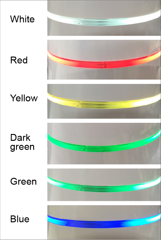
The following shows the color sample of LED.
The colors could look different from the actual colors depending on the monitor you use and/or lighting condition of the environment.
ID : 7147