ID : 4848
Changing the Z-axis Stroke of 135 mm Mechanical Ends
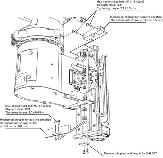
To limit the changing motion range of the 3rd axis (Z-axis), mechanical stoppers for positive direction (upwards) and/or the negative direction (downwards) need to be mounted.
Prepare mechanical stoppers that allow the robot motion in your desired range, referring to the drawings on later pages.
Move the Z-axis unit so that the mechanical stopper can be mounted on the specified position. After turning off the motor and controller power, mount the mechanical stopper. Make sure that the Z-axis brake is NOT released while mounting the stopper.
XR Series
- Drawings of the 3rd axis (Z-axis) Mechanical Stopper for Negative Direction (XR Series, Z-axis stroke: 135 mm)
- Drawings of the 3rd axis (Z-axis) Mechanical Stopper for Positive Direction (Z-axis stroke: 135 mm or 200 mm)

Do NOT move the 3rd axis (Z-axis) by hand.
To mount the mechanical stopper for positive direction, a plate mounted on the extension plate needs to be removed. Keep the plate in a safe place as it is used to CALSET.
XR2
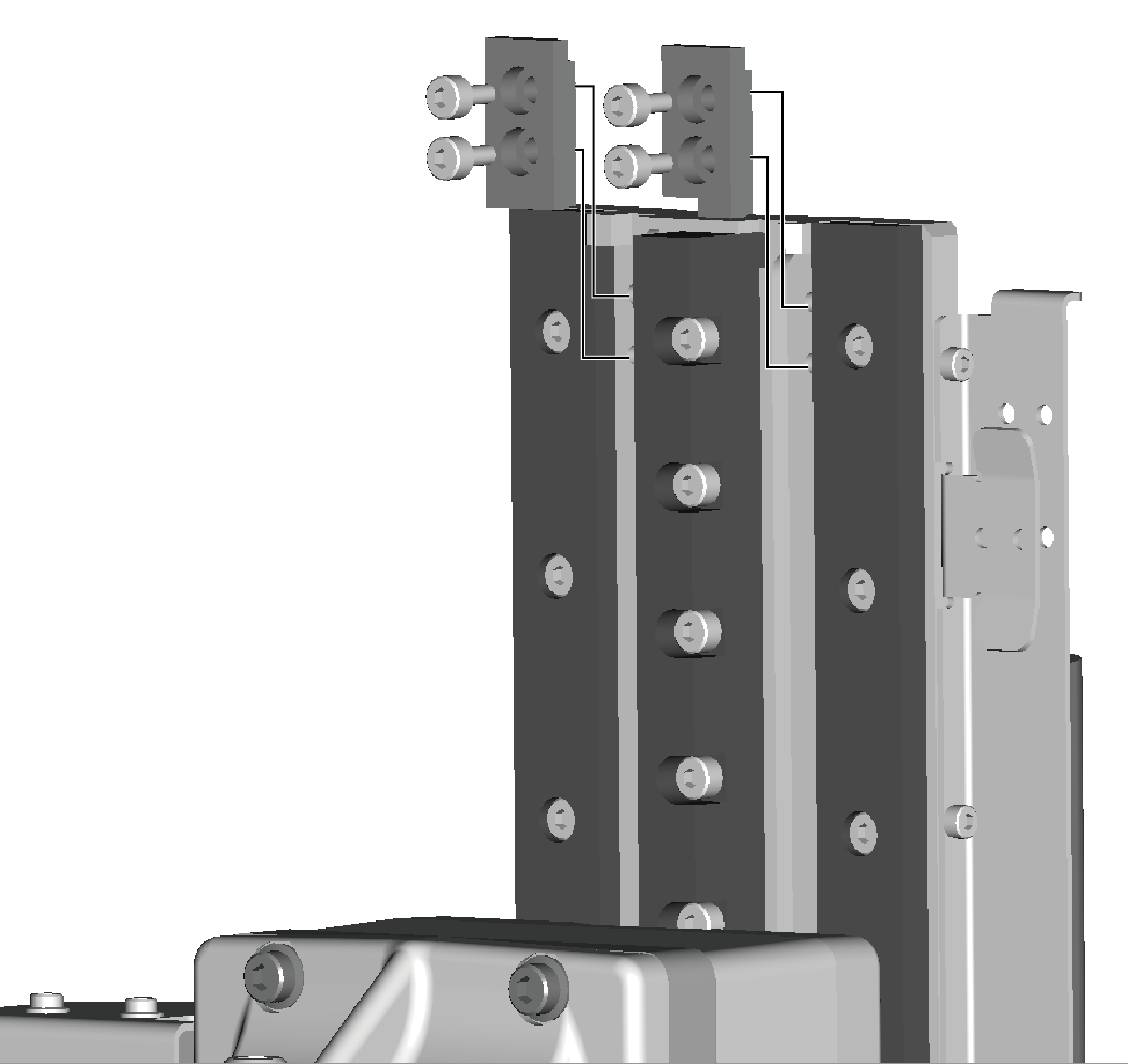
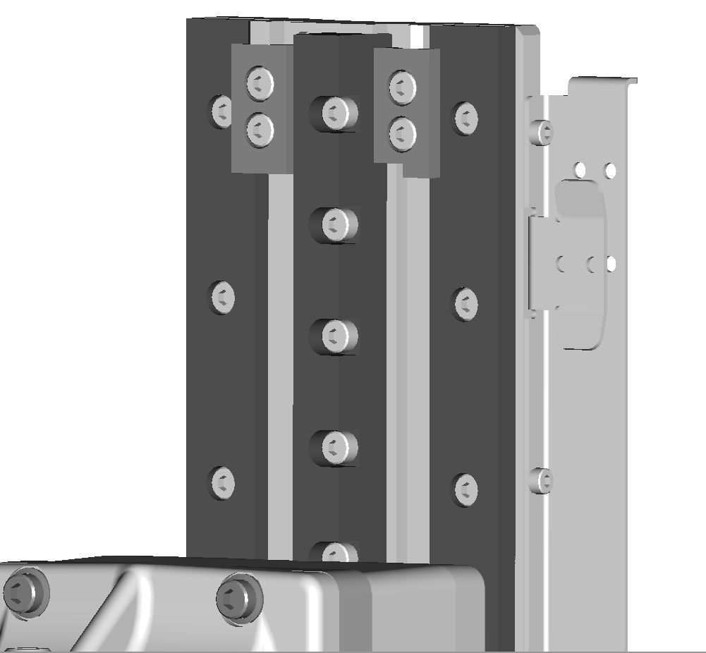
- Drawings of the 3rd axis (Z-axis) Mechanical Stopper for Negative Direction (XR2)
- Drawings of the 3rd axis (Z-axis) Mechanical Stopper for Positive Direction (Z-axis stroke: 135 mm or 200 mm)
The mechanical stopper on the third-axis positive direction is same as that of the XR series. Please refer to the diagrams above.
For the mechanical stopper on the negative direction, install as follows.
 |
 |
ID : 4848
- Related Information
- Drawings of the 3rd axis (Z-axis) Mechanical Stopper for Negative Direction (XR Series, Z-axis stroke: 135 mm)
- Drawings of the 3rd axis (Z-axis) Mechanical Stopper for Negative Direction (XR2)
- Drawings of the 3rd axis (Z-axis) Mechanical Stopper for Positive Direction (Z-axis stroke: 135 mm or 200 mm)

