
ID : 2889
Calibration Procedure for the Camera
Place three workpieces or marks; which become reference points for the calibration, on the turntable. Using these reference points, measurement results of the camera, and teaching results of the robot, measure the exact positional relationship between the camera and robot.
The following shows the camera calibration procedure.
Each turntable needs to be calibrated respectively.
1 Confirmation of the Calibration Procedure
Instructional video of the calibration procedure is played. Once the video ends, press [Next].
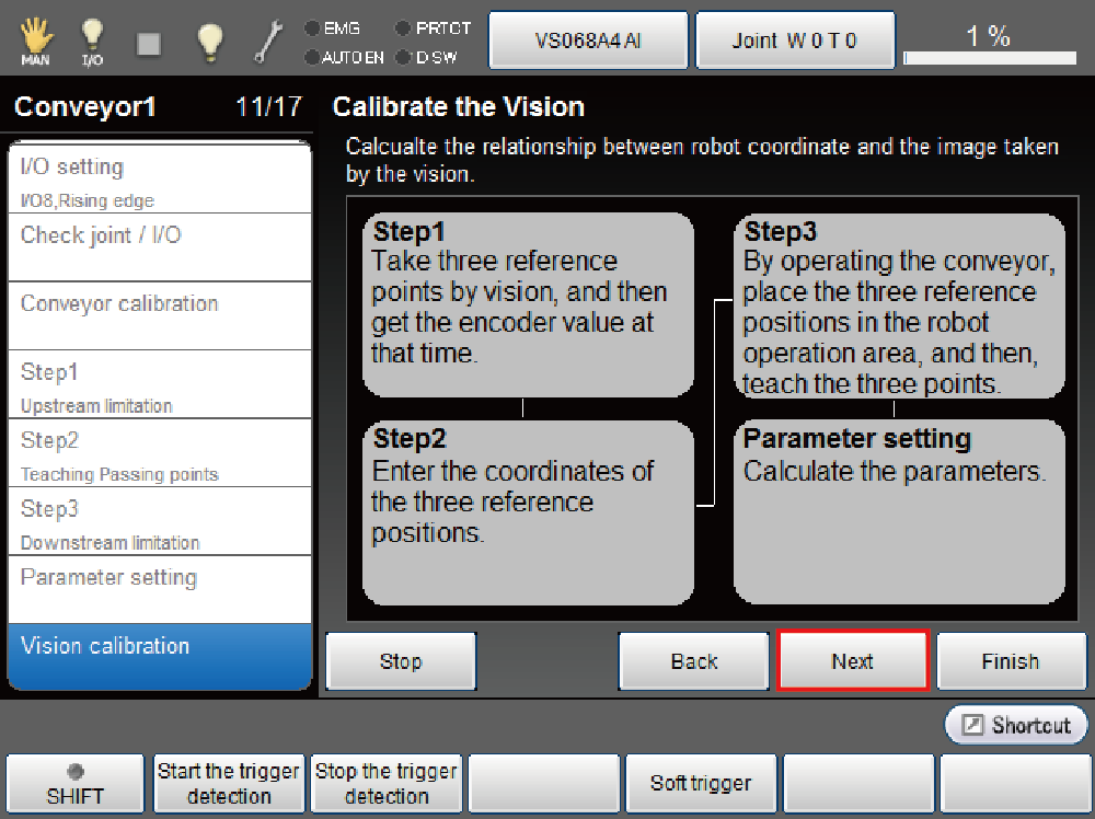
2 Obtaining the Encoder Value of Shooting Position
Shoot 3 criteria point by vision and obtain the encoder value of shooting position.
Place three reference points on the turntable. Then shoot these points by vision.
Obtain the encoder value of the shooting position by pressing [Get detected encoder value] button.
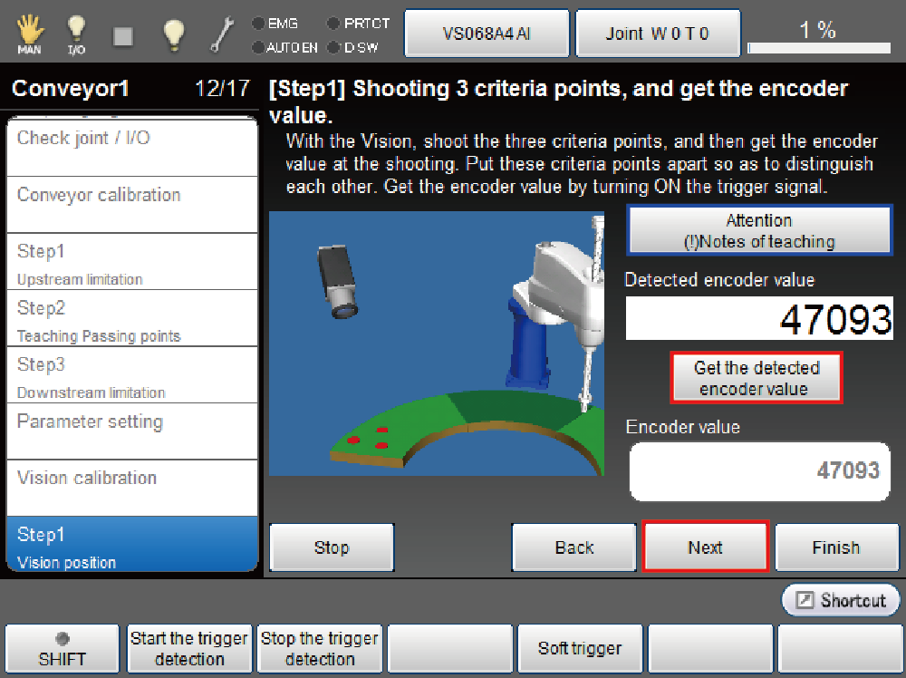
When you press [Attention (!) Notes of teaching] button, the detailed information for teaching will be displayed.
Press [OK] - [Next].
3 Entering the Vision Coordinates of Reference Point
Enter the vision coordinates of reference point taken by camera.
Once selecting visual coordinates for each reference point, the ten key is displayed. Enter the value then press [OK] to confirm.
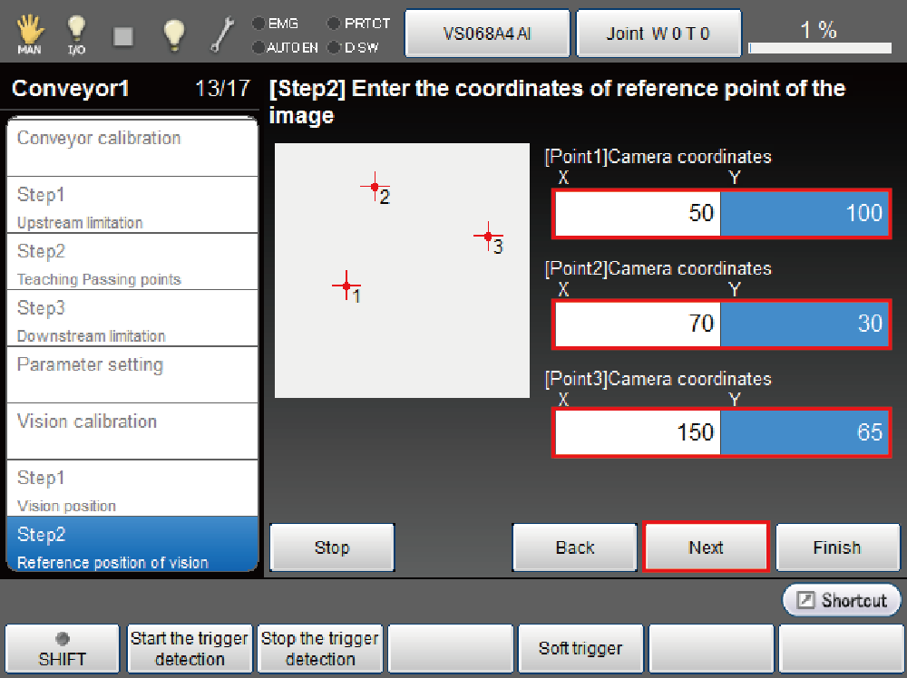
Once all vision coordinate's settings are complete, press [OK].
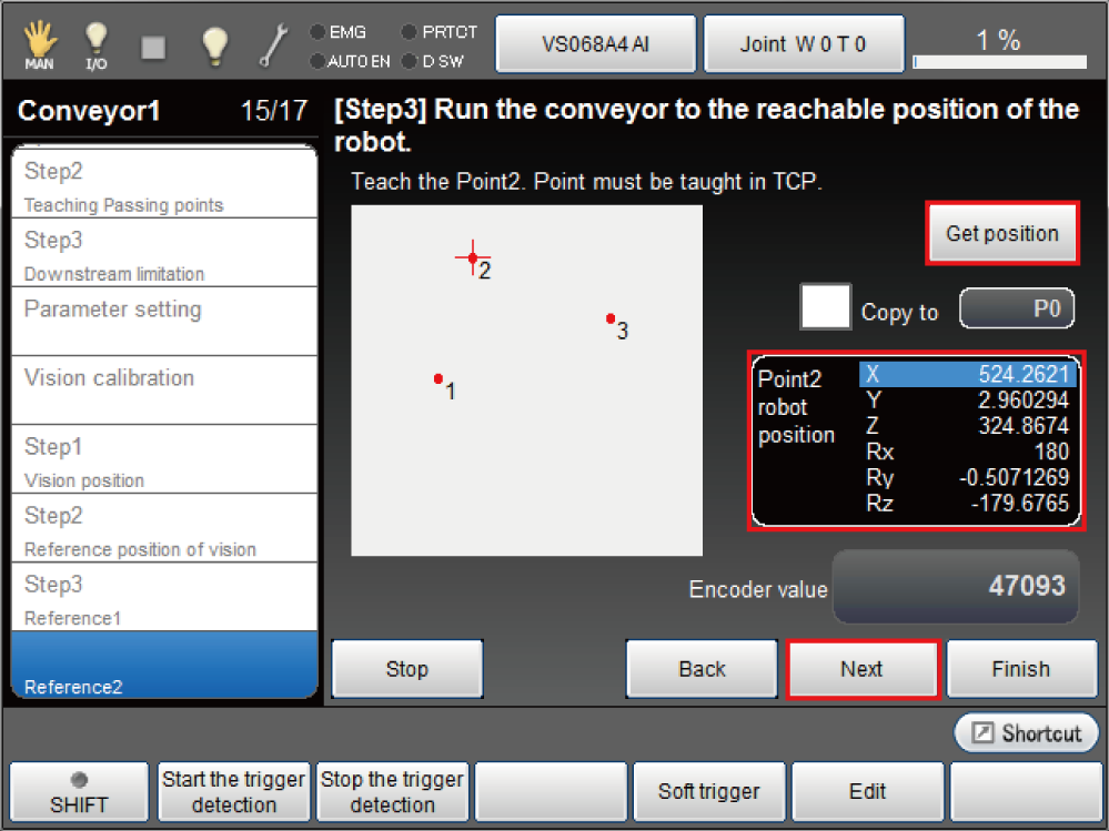
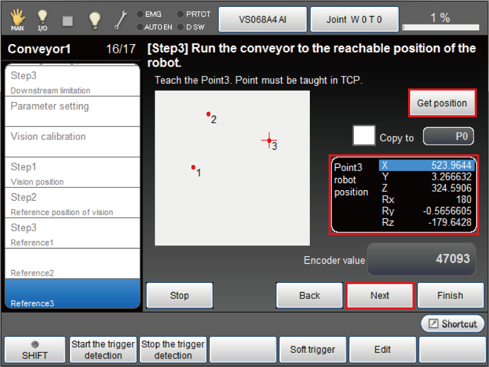
4 Obtaining the Robot Coordinates of Reference Point
Teaching the reference point 1.
Start the turntable then move the reference point to the range where the robot can teach.
Move the robot to the place where the end effectors can grip the reference point. Press [Get Position] at the TCP point.
- Move back the reading position of reference point 1 in the opposite of the conveyor vector direction to get the vision sensor detection position.
- The height of gripping at the tracking motion is determined by a plane created by three reference points.
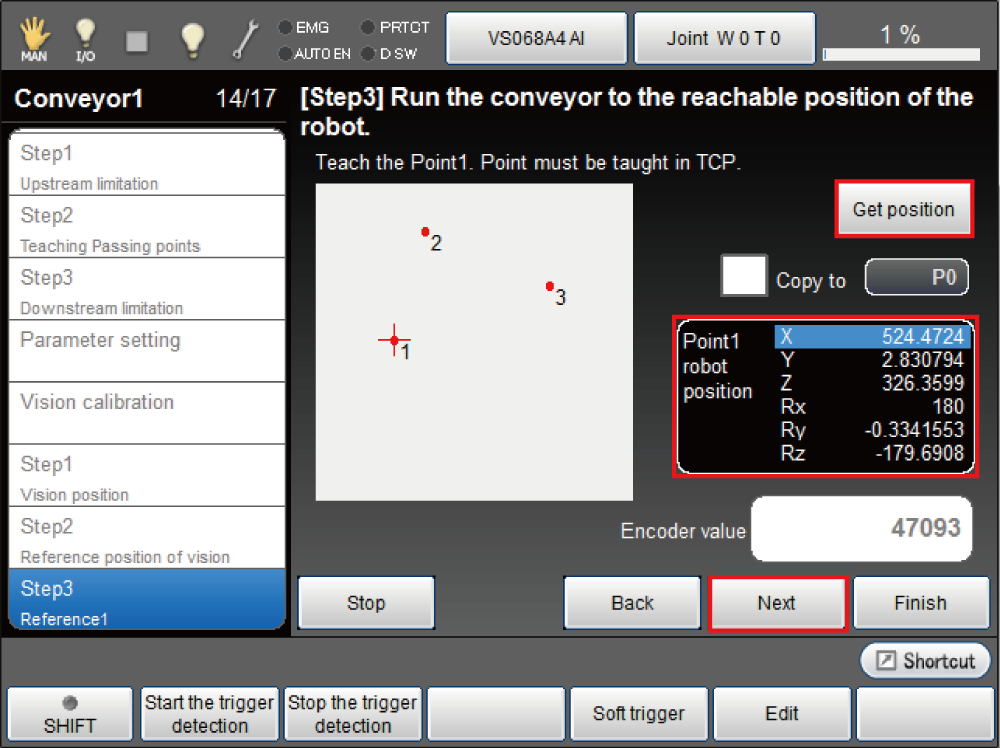
Check the obtained position, and then press [Next] if everything is satisfactory.
To teach reference point 2 and 3, perform STEP 1 and STEP 4 again.
The obtained coordinate values can be changed. To do so, press the edit button on the bottom of the screen. Ten keys are displayed. By the ten keys, change each coordinates values.
5 Confirmation of the Calibration Result
Check the calculated parameters, and press [Finish] if everything is satisfactory.

6 Applying the Calibration Result
System message is displayed. Press [OK] if everything is satisfactory.
Calculated data is set to the controller.
The setting change is not confirmed if [Cancel] is pressed.
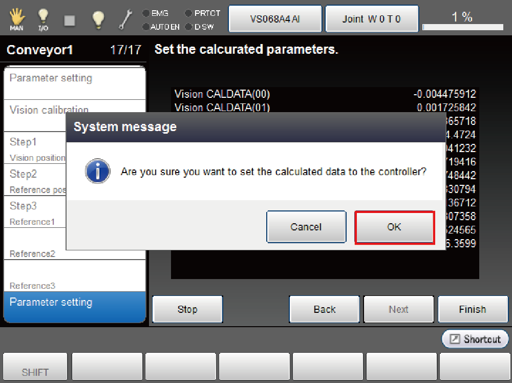
The setting change is confirmed and returns to the "Tracking" window.
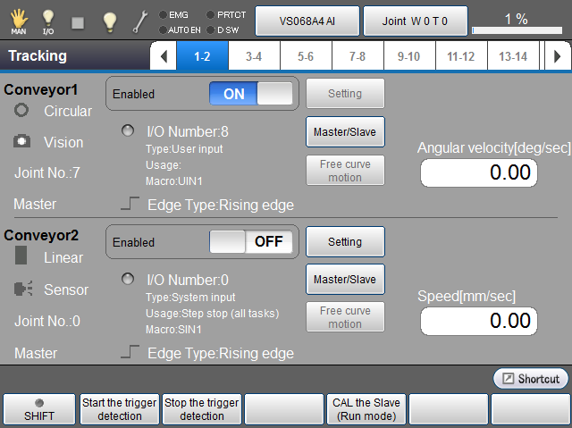
For the installation of one turntable and one robot, this is the end of the setup.
ID : 2889