
ID : 3324
HSR and HSA1 Combination
This page describes the system configuration and the details in the following sections.
- System Configuration Layout
- RC8 Series-Supported Robot-Related Components
- Selective Joint-Related Components
- Attention
System Configuration Layout
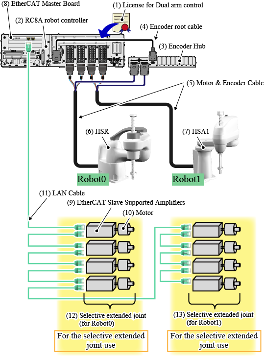
The following figure illustrates the overall system configuration.
(The following example shows the system that controls an HSR and an HSR1.)
RC8 Series-Supported Robot-Related Components
| Components /(Part No.) |
Description |
|---|---|
(1) License for Dual arm control |
For details, refer to "License". |
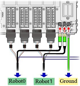
(2) RC8A robot controller |
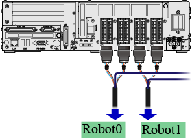
A controller to control two robots (an HSR and an HSA1). It has three earthing terminals for robot. Connect as follows.
For details about external view and specification, refer to "RC8 SERIES ROBOT CONTROLLER MANUAL". |
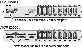
(3) Encoder Hub(4) Encoder root cableEncoder hub and encoder root cable are sold as a set. There are two types of sets; old model and new model.
For both types, the length of the encoder root cable is approximately 0.4 m. |
Encoder HubCollects the encoder signal of each robot and sends them to the RC8A series robot controller. Only the new model is available in the above system.
For details about the external diagram and the precaution on installation, refer to "Encoder HUB". Encoder root cableA cable to connect an encoder hub and an RC8A robot controller. Note that the encoder hub of new model does not accept the encoder root cable of old model. For the encoder root cable of new model, use the encoder hub of new model. |
(5) Motor & Encoder Cable |
An encoder line connects to an RC8A robot controller through an encoder hub. |
(6) HSR |
A robot that runs as a "ROBOT 0". For details about external view and specification, refer to "HSR SERIES USER'S MANUAL". You can use an HSA1 as ROBOT0. Viewing from the RC8A robot controller side, a robot connected to the motor connector on the left end is Robot0. The next robot is Robot1.
|
(7) HSA1 |
A robot that runs as a "ROBOT1". For details about external view and specification, refer to "HSA1 SERIES USER'S MANUAL". You can use an HSR as ROBOT1. |
Selective Joint-Related Components
When you use an selective extended joint, refer to the followings.
| Components | Description | ||||||||||
|---|---|---|---|---|---|---|---|---|---|---|---|
(8) EtherCAT Master Board |
Enables the EtherCAT communication with selective joints. To use this board, you need to prepare a software license. There are four types of software license-board combinations as follows.
|
||||||||||
(9) EtherCAT Slave Supported Amplifiers |
Available amplifier are predetermined. In the "SELECTIVE EXTENDED JOINT (ETHERCAT) MANUAL", in the "Hardware Connection Structure", refer to "EtherCAT Slave Supported Amplifier". |
||||||||||
(10) Motor |
A motor for a selective joint. Select a motor that can run with the EtherCAT Slave-supported amplifier to use. | ||||||||||
(11) LAN Cable |
EtherCAT communication cable. Use a twisted pair LAN cable of category 5 or higher. Either a straight- or a cross-LAN cable can be used.
|
||||||||||
(12) Selective extended joint (for Robot0) |
To use an extended joint, connect the extended joint as the figure above. The number of axes available for one robot is from 0 to 4. Whether the target extended joint belongs to Robot0 or Robot1 is determined by the order of connection of EtherCAT Slave-supported amplifier. An EtherCAT Slave-supported amplifier which connects to the EtherCAT master board first will be assigned to the 5th-axis of Robot0. The next amplifier will be assigned to the 6th-axis of Robot0. For further information, refer to "Selective Joint Assignment to Each Robot". |
||||||||||
(13) Selective extended joint (for Robot1) |
Attention
-
Before connecting each device, read the following linked pages carefully for safe operation.
Connect an RC8 series-supported robot - "Installation" in the "RC8 SERIES ROBOT CONTROLLER MANUAL"
- "Installing Robot Components" in the "HSR SERIES USER'S MANUAL"
- "Installing Robot Components" in the "HSA1 SERIES USER'S MANUAL"
Connect a selective joint "Hardware Connection Structure" in the "SELECTIVE EXTENDED JOINT (ETHERCAT) MANUAL" -
Before the system design and/or operation, read the following linked pages carefully for your safety.
About RC8 series-supported robot About Selective joint "SELECTIVE EXTENDED JOINT (ETHERCAT) MANUAL"
ID : 3324