
ID : 26
Connectors
This section shows the connectors on the robot unit.
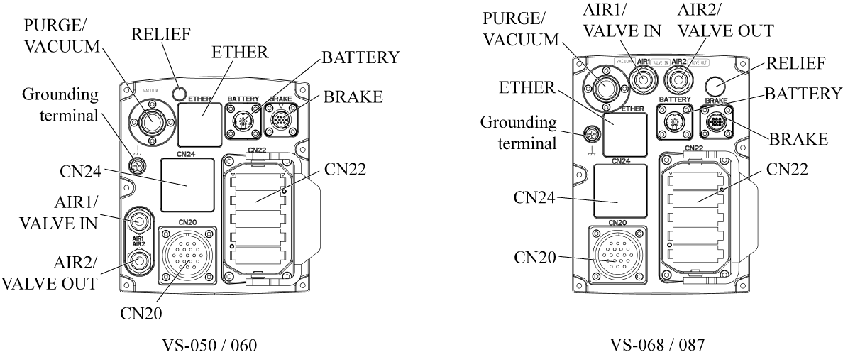
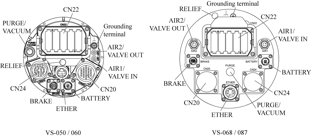
Connector Panel
Rear Connector Panel
Bottom Connector Panel
Details of Connectors
| Connector name | Description | Remarks |
|---|---|---|
| CN20 | Connector for hand signals Connected to CN21 on the tool wiring panel. | Use attached connectors for wiring. Not provided on robots having no signal lines or air piping. |
| CN22 | Connector for motor & encoder cable | |
| CN24 | Connector for hand signals Connected to the signal wiring connector on the communication interface flange. | Use attached connectors for wiring. Provided on robots having a communication interface flange-A. |
| AIR1 / VALVE IN | Joint for air to be supplied to solenoid valves. (PT 1/4) (* 1) | Not provided on robots having no signal lines or air piping. Maximum Air Pressure: 0.49MPa (71PSI) |
| AIR2 / VALVE OUT | Directly connected to AIR2 on the tool wiring panel. (PT 1/4) | Not provided on robots having no signal lines or air piping. Maximum Air Pressure: 0.49MPa (71PSI) |
| For clean room type, exhaust port of solenoid valves | Required to install exhaust treatment piping | |
| BATTERY | Connected to an external battery unit. | - |
| BRAKE | Connected to a brake release unit. | - |
| ETHER | Connected to the Ethernet cable. (*2) | Provided on robots having a communication interface flange-A |
| PURGE / VACUUM (*4) | Connected to the air purge unit. (PT 1/4) | Provided on protected type robots (IP67). The source air pressure is 0.01 to 0.03MPa. (*3) |
| For clean room type (ISO class3), exhaust port of solenoid valves. (*5) | Recommended vacuum flow rate.
40 - 55liter / min (VS050, 060) 60 - 75liter / min (VS068, 087) |
|
| RELIEF | Protected type robots (IP67) have an M5 exhaust port in RELIEF. After the PURGE operation, to adjust the internal pressure, air will be emitted from the exhaust port once the pressure exceeds the certain limit. |
The exhaust port does not require any treatment for use. You can connect an extension tube to the exhaust port to expel air at the different area, however it could deteriorate the protection performance because the air resistance will be increased. |
| GROUND (*6) | Grounding terminal (Functional ground) | M5 |
*1: To AIR1, supply dry air filtered through an air filter (recommended filtration rating: 5 μm or below). Before piping, blow the air tube out with dry air to clean out the inside (flushing); otherwise, any chips, cutting oil, dust or dist remaining in the air tube may result in a damaged valve.
*2: To the Ethernet cable, use the shielded flex resistance LAN cable. When using an Ethernet cable, install the ferrite core as close as possible to the connector panel, and then secure it with one of the tie bands provided.
*3: To PURGE, apply the specified air pressure. Connecting air prepared for hands mistakenly may lose the ingress protection.
*4: Please prepare an exhaust air tube by yourself.
Exhaust port size Outer φ16 mm Inner φ12 mm
Be sure to fix the exhaust port and the exhaust tube tightly to prevent gaps by means of hose clipper, etc. If the amount of exhaust does not meet the recommended flow rate, it may affect the clean level due to the exhaust air leakage into the robot body.
Recommended blower: Manufacturer: Teral Inc. Model: VFZ081PN
*5: An exhaust port is equipped only for a clean room type robot designed for ISO class 3.
Since a clean room type robot for ISO class 5 does not equip an exhaust port, the hall is plugged with a protective cap. Do not remove the cap.
*6: Terminals are indicated by the Earth ground symbols.
Tool Wiring Panel
Tool wiring panel is provided only for the signal lines & air piping type robot.
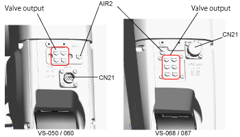
| CN21 | Connector for hand signals Use attached connectors for wiring. |
| AIR2 |
Directly connected to AIR2 on the connector panel. (M5) Not available for clean room types. |
| Valve output | Air piping joint for hands (M5) |
ID : 26