ID : 4837
Changing the Mounting Position of T-axis Unit
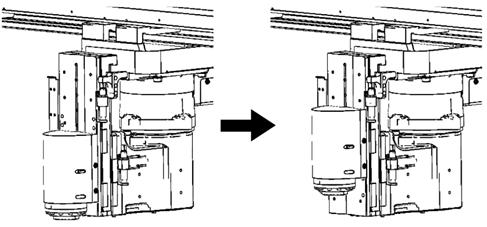
The XR series of robots allows the T-axis unit to be shifted by 40 or 80 mm in the positive direction of the Z-axis from the original mounting position as shown below.
The T-axis unit is mounted on the robot unit with four bolts (M5) and two positioning pins (f5).
After changing of the mounting position, the Z-axis coordinates in software can be used without modification.
Shifting the T-axis unit may cause the end-of-arm-tooling (EOAT) to interference with the Z-axis’ movable components.
 |
|
Mounting example of T-axis unit shifted by 40 mm in the positive direction
|
Removing the Four Bolts from the T-axis Unit
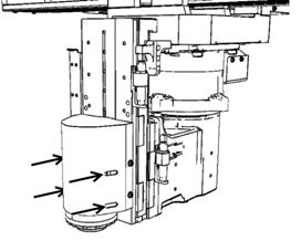
Remove the four bolts shown below then dismount the T-axis unit.
When loosening those bolts, be sure to support the T-axis unit by hand; otherwise, the T-axis unit will drop.
 |
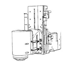 |
| Bolt positions (4 locations) when R=200 mm Insert an Allen wrench (4 mm) through the slots provided in the T-axis unit and remove the four bolts (M5). (The T-axis unit is designed so that those bolts will not drop.) | Bolt positions (4 locations) when R=250 or 300 mm |
Securing the T-axis Unit
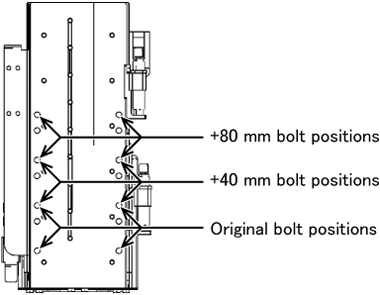
The allowable shift amount is 40 or 80 mm in the positive direction of the Z-axis.
Tightening torque: 5.9 ±0.6 N▪m
Engineering-design Notes for Robot End-of-arm-tooling When the T-axis Unit is Shifted
Shifting the T-axis unit may cause the robot end-of-arm-tooling to interfere with the robot unit. It depends upon the arm length of the R-axis. Design the robot end-of-arm-tooling so that no interference occurs.
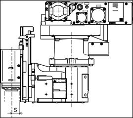
| Arm length of R-axis | S (Distance between T-axis and robot unit |
|---|---|
| 200 mm | 25 mm |
| 250 mm | 75 mm |
| 300 mm | 125 mm |
While changing the mounting position take care not to pull, scratch, or damage the T-axis wiring.
ID : 4837

