
ID : 18101
Force Sensor Mounting Stay
To install a force sensor to a flange of a robot, the dedicated stay (force sensor mounting stay) needs to be made by customers. This section describes the force sensor mounting stay in the following subsections.
Structure of Force Sensor Mounting Stay
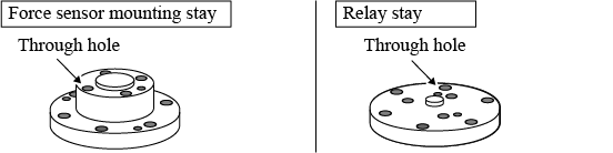
The following shows an example of the force sensor mounting stay.
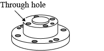
For the force sensor mounting stay, make multiple through holes as above so that bolts and dowel pins can be inserted.
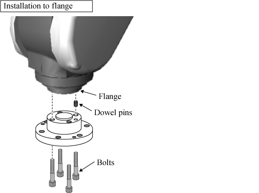
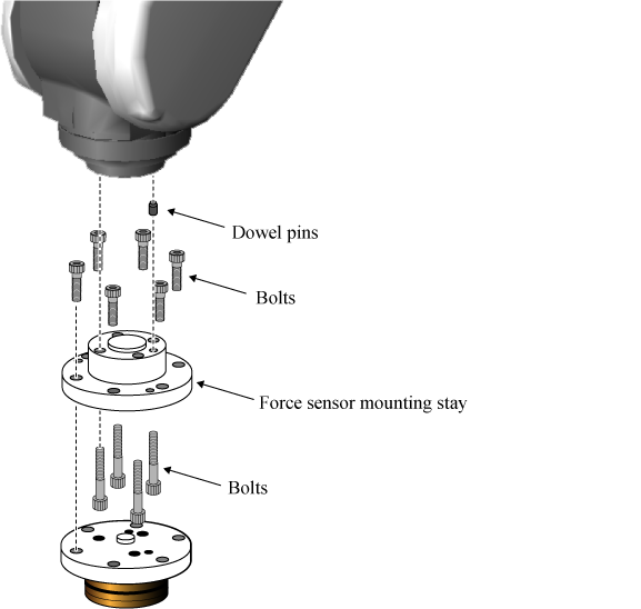
To install the force sensor mounting stay to the flange of the robot, use dowel pins and bolts as shown below.
(Dowel pins and bolts should be prepared by customers)
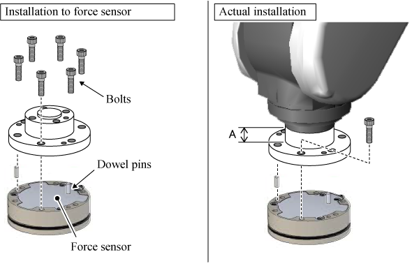
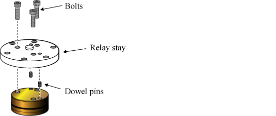
To install the force sensor mounting stay to the force sensor, use dowel pins and bolts as shown in the lower-left figure.
In actual, install the force sensor mounting stay to the flange of the robot, and then install the force sensor. Therefore, dimension A in the lower-right figure needs to be high enough to tighten bolts.
Key Point when Designing Force Sensor Mounting Stay
-
Dimension of screw on the flange surface and total mass of tool/stay/force sensor
-
For positions and dimensions for screw holes on the flange surface and holes of dowel pins, they are written in the dimensional outline drawing of the robot to be used.
For the total mass of an equipment that applies payload to a flange such as a stay/force sensor/tool (hereafter, "tool-related part") and the position of its center of gravity, the upper limit differ depending on the robot to be used.
For details, refer to the following links.
Robot series Dimensional outline drawing / Precautions of tool-related part
(Link destination)
6th axis VM VS VS-6556/6577 VP 4th axis HM (including HMS) HS (including HSS) HSA1 HSR XR Dimensions of hole of force sensor
-
For positions and dimensions for the screw hole of force sensor and the hole of dowel pin, refer to the dimensional outline drawing of the force sensor to be used.
Positions of the screw holes of the flange and the force sensor are close
-
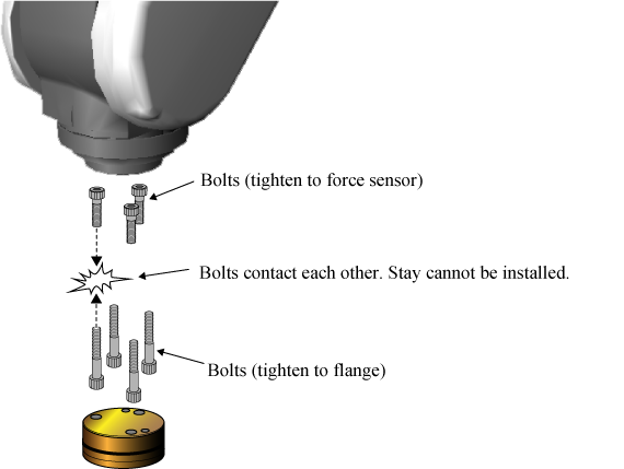
If positions of the screw holes of the flange and the force sensor are close (example: a pitch circle diameter (hereafter, "P.C.D.") of the screw hole of the flange and P.C.D.of the screw hole of the force sensor are very close), both bolts interferes each other as shown below. The standard stay cannot be installed. In this case, install the relay stay additionally.
-
The following is an example of the force sensor mounting stay and the relay stay.
-
First, install the relay stay to the force sensor.
-
Next, install the force sensor mounting stay to the flange. After that, install the relay stay with the force sensor to the force sensor mounting stay.
-
By designing positions of each hole of the force sensor mounting stay and the relay stay so as not to interfere each other, it allows to install as above.
ID : 18101