
ID : 2842
Precautions Before Operating
This section explains about the necessary precautions before operating the safety motion.
Contents applied to your application may differ depending on the difference of the model of engine board mounted in the robot controller.
For Safety Use of Safety Motion
- Safety Motion specification equips the safety function that allows operators and robots to work together (co-operation) in the same operation area without safety fence. Before using the robots in the co-operation, be sure to perform the risk assessment of the target robot system, take necessary safety measures. and confirm that the risks to human are sufficiently reduced.
- Safety Motion specification observes the robot position and the speed in order to stop robot motion when the robot digresses from the predetermined range. This function is not to limit the power of robot automatically when the robot touches the human body or other things.
- If you set the device of human body detection, such as light curtains, etc., be sure to the matters as follows:
- Set the device of human body detection back further from the minimum distances in order to detect hazards; so the robot is able to stop before the human body reach the hazard zones. This is according to Safety Distance Calculation (ISO 13855, etc.,).
For Safety Distance Calculation, consider the stopping distance may differ depending on the movement speed of the robot.
For further information about stopping distance, refer to handling manuals for respective robots. - If the approach to the detection device of the human body is not defined and the safety distance is out of range to the human body detection, the security cannot be guaranteed.
Set up for safety measures, such as safety fences.
- Set the device of human body detection back further from the minimum distances in order to detect hazards; so the robot is able to stop before the human body reach the hazard zones. This is according to Safety Distance Calculation (ISO 13855, etc.,).
Effects on the Existing Functions
In RC8A(safety motion) robot controller, there are "Functions not Available in Safety Motion", "Functions where an Error may be Detected" and "Functions whose Usage is Limited" for RC8A(standard) robot controller. For details, refer to "Effects on the Existing Functions".
Particular Errors of Safety Motion
The following shows the particular errors of safety motion.
Error: When Motor ON for First Time Use
The error may occur when the motor is first turned ON after purchase due to the software motion limit.
This is because the axis is moved out of software motion limit when packing, not a breakdown. Release the error either of the following strategies.
- Release the motor break, and move the robot into the software motion limit manually.
- Even if the error of the software motion limit occurred, set the "monitoring disable input parameter" valid in order to operate the robot with teach pendant or mini-pendant, and turn the monitoring disable input signal (short-circuited) ON. Then, get the robot to move into the software motion limit manually. After the error released, if you won't use the monitoring disable input signal, set the "monitoring disable input parameter" disable.
Error: When Using External Power Source to Mini I/O and Motion I/O Power Supply
When using the external power source to Mini I/O and Motion I/O power supply, if you turn on the power to the robot controller without supplying the external power, or supply the external power after that of the robot, an error may occur and fail to operate the robot as a result.
Be sure to supply the external power before the robot controller will be powered ON.
Connection to Devices with Each Signal of Mini I/O and Motion I/O
There are features and cautions when connecting to the devices with each signal of Mini I/O and Motion I/O as follows:
Features
Basically, safety circuits, such as Enable Auto input (Mini I/O), SS1(Motion I/O), are able to connect to contacts (switches and relay contacts) exclusively. Additionally, the following signals are able to connect to the output signals on safety sensor (transistor output) directly. (Hereafter, "Sensor-connectable-input")
| The model of engine board mounted in the robot controller | Sensor-connectable-input |
|---|---|
| N, 7 |
|
| E, C |
|
The system in which the area sensor detects the human body and stops the robot is possible by connecting the signal of area sensor to SS2.
The above input signal has parameters to be set, which ask whether the signal to be input is "contact" or "transistor output". When shipping a robot controller, as the input signal is set "contact", you need to change the setting when connecting the safety sensor. For details, refer to the following precautions.
Precautions
- Devices which connect to Mini I/O, Motion I/O should be conducted the risk assessment, and then select the devices which meets the requirements of the safety measures.
- Power-supply to Mini I/O and Motion I/O should be the same one.
- When connecting a safety sensor to the sensor-connectable-input (see the table in [Feature]), pay attention to the following points.
- If you intend to connect a safety sensor with the input, select a safety sensor that satisfies all of the following requirements.
・Safety-certified sensor
・Its output is PNP open collector type
・Output is duplicated
・It outputs OFF-pulse
・OFF-pulse of duplicated two outputs are not overlapped
・Output is negative logic (becomes functional at Low level) - The logic of sensor-connectable-input is negative logic, which becomes functional at Low level. For safety sensor, use the output signal is negative logic.
- Sensor-connectable-input sees if OFF pulse (turns to Low level instantaneously during the state of High level) is entered periodically to check if the functions of devices connected work normally. If OFF pulse is not entered, it may result in an error, select the safety sensor which meets the necessity measures for OFF pulse output.
The model of engine board mounted in the robot controller Pulse Specification N, 7 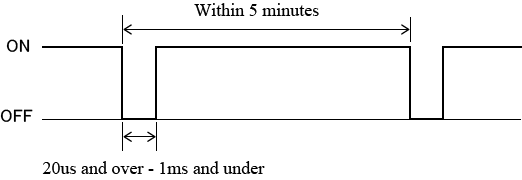
E、C 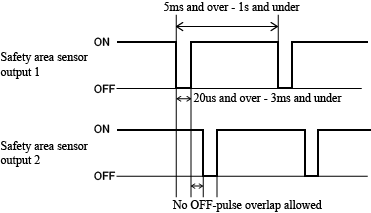
- You need to change setting of input for sensor-connectable-input. After setting the parameters by using WINCAPSIII, send the necessary data for monitoring with RC8A Safety parameter tool to the robot controller, and restart the robot.
Operation path : [Project] - [Parameter]- Safety No. Name of Setting Setting of Safety Sensor When Connecting 28 Area sensor SS2 input setting Enable:1, input to connecting the safety sensor 29 Area sensor RSM1 input setting 30 Area sensor RSM2 input setting 31 Area sensor RSM3 input setting 32 Area sensor TOOL0 input setting(*) 33 Area sensor TOOL1 input setting(*) 34 Area sensor TOOL2 input setting(*) 35 Area sensor TOOL3 input setting(*) 36 Area sensor monitoring area 0 disable input setting(*) 37 Area sensor monitoring area 1 disable input setting(*) 38 Area sensor monitoring area 2 disable input setting(*) 39 Area sensor monitoring area 3 disable input setting(*) 40 Area sensor monitoring disable input setting(*) 41 Area sensor SS1 input setting(*) 42 Area sensor Safe Homing input setting(*)
(*) Available only when the model of engine board mounted in the robot controller is "E" - Power-supply to the safety sensor should be supplied from the power-supply unit of Mini I/O and Motion I/O.
- The number of connecting pins which allocates to respective sensor-connectable-input is 4. Two pins are used for each one line in order to connect a contact to dual lines. If you connect the safety sensor, connect only one pin per one line, and let the other pins OPEN.
For example, if you connect the safety sensor to SS2, the allocated pins are four pins as shown below. (See "Motion I/O Input Signal Pin Assignment")
Port No. Name Port No. Name 1 SS2 input 1-1 35 SS2 input 1-2 17 SS2 input 2-1 51 SS2 input 2-2
For these four pins, the pin which connects the safety sensor is Line1, Port No. 35, and Line 2, Port No. 51. Port No. 1 and 17 is OPEN.
Connecting pins can be distinguished by the names. The names of sensor-connectable-input are defined as follows:
Signal name m-n
"m" describes Line, "n" describes dividing of pins. Connect the safety sensor to the pin which is "n" = "2".
For a specific example, see "Examples of Connection Circuit of Safety Sensor"
- If you intend to connect a safety sensor with the input, select a safety sensor that satisfies all of the following requirements.
- Output signal of safety circuit outputs pulse, which reverses the state instantaneously, in order to check if the functions of devices can work normally. Thus the devices to be connected should be the ones which do not cause improper operation even if pulse outputs.
List of output signals which output pulse and the specifications of pulse is as follows:
Output signals of Motion I/O are all PNP type signals.
- List of output signals which output pulse
Signal name Connector Signal type Auto Mode Mutual Monitoring Output Mini I/O NPN type/PNP type
(select one when you make an order of robot controller)SOS output Motion I/O PNP type only SLP output RSM1 output RSM2 output RSM 3 output RPM output Safe Reference Position Check Output - Pulse Specification
(*1) The model of engine board mounted in the robot controllerModel (*1) Output signal state Pulse Specification N, 7 ON(*2) 
OFF(*3) 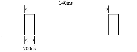
E、C ON(*2) 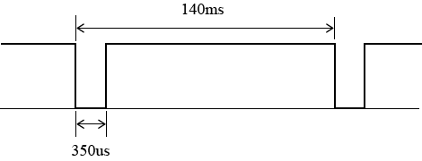
OFF(*3) 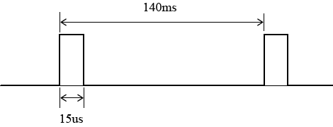
(*2) Generate OFF-pulse when the output signal is ON
(*3) Generate ON-pulse when the output signal is OFF
- List of output signals which output pulse
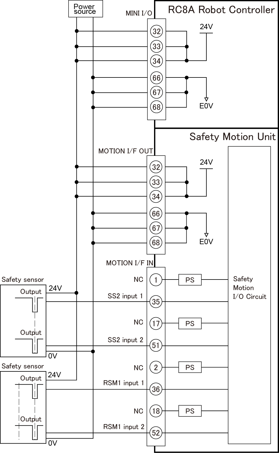
Examples of Connection Circuit of Safety Sensor
The following is examples of connection circuit
- Precondition
- Power supply to Mini I/O, Motion I/O : the external power source
- Connect the safety sensor to SS2, RSM1
- Examples of the connection circuit of the safety sensor
- Setting Parameters
Operation path of WINCAPSIII: [Project] - [Parameter]- Safety No. Name Setting 28 Area sensor SS2 input setting 1: Enable 29 Area sensor RSM1 input setting 1: Enable 30 Area sensor RSM2 input setting 0: Disable 31 Area sensor RSM3 input setting 0: Disable
Precautions: When Sending "the necessary data for monitoring"
After you send "the necessary data for monitoring" to the robot controller, if you turn off the robot controller, wait for 10 seconds to turn OFF the power.
If you don't wait for 10 seconds, the error which tells that forwarding safety parameters uncompleted may occur, next time.
If an error occurs, re-send "the necessary data for monitoring" to the robot controller, and then wait for 10 seconds to turn OFF the power.
Precautions: When Using MC8A Safety Motion Specification
When using MC8A Safety Motion Specification, beware not only the above mentioned, but also the following matters.
- Robot Position Monitoring (RPM) is unable to use.
You need to disable Monitoring Area Disable Input because Position Monitoring (RPM) is unable to use.
First, execute [Project] - [Parameter] with WINCAPSIII, and Disable: 0 all the safety parameters of No.11-14(Monitoring area 0 -3 disable input setting), and then save the project. Next, send "the necessary data for monitoring" to the robot controller with RC8A Safety parameter tool, and then restart the robot controller. - Do not create monitoring areas with WINCAPSIII.
If you create monitoring areas with WINCAPSIII and execute [Monitoring area data output], (see "Creating and Saving Monitoring Models"), an error may occur as a result when opening the project with RC8A Safety parameter tool. If you execute [Monitoring area data output] by mistake, newly create the project again.
ID : 2842