
ID : 5641
Installation of Cableveyor Holder and Guide
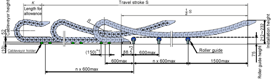
If the stroke exceeds 4500 mm, supply a cableveyor holder and guide.
The cable may be break due to friction unless the cableveyor, the cableveyor support or the guide are installed properly. Be sure to install each of these components properly.
Installation Diagram
 |
Requirements for the Installation of the Cableveyor Holder and the Guide
The cableveyor holder reduces friction between the cableveyor against the cradle.
- If the stroke exceeds 4500 mm, supply a cableveyor holder and guide.
- Install the roller guide and and the cableveyor holder at an interval of 600 mm or less.
Cableveyor Holder
Cableveyor reduces the friction between the cables and cradles.
- A semicircle cableveyor holder is recommended. " Reference Drawing of Cableveyor Holder (PDF:77KB) "
- We recommend preparing cableveyor holders for each corner if the bottom side of the cableveyor interferes with corner of pillars and other obstacles.
When you use the supports illustrated in Reference drawing of mount (1200 mm stroke)(PDF:72KB) on Mount Example
・Prepare two piece of cableveyor holders for each pillar (Refer to gleen semicircles in the above drawing)
・Install the cableveyor holders at an interval of 150mm along with the 4×N5(drill hole) on the supports. *1
Guide
The guide supports and guides the cableveyor.
- Roller guides are recommended. " Reference Drawing of Roller Guide (PDF:126KB) "
- Arrange the guides to support the cableveyor at the level of 75mm.
- The distance between the first link center on the fixed point and the guide located on the nearest from the fixed end must be less than or equal to 88.5mm.
Glide Shoe
If the stroke exceeds 8000 mm, the cableveyors may be abnormally worn due to abrasion with each other. To decrease abrasion, install a glide shoe on a lower cableveyor area that is likedly to be worn.
| Item | Manufacturer | Model |
|---|---|---|
| Glide shoe | Tsubakimoto Chain Co., Ltd. | TKP58H39-GS |
ID : 5641