
ID : 2486
Modeling Overview of Monitoring Target and Restricted Area
Monitoring Target and Restricted Area
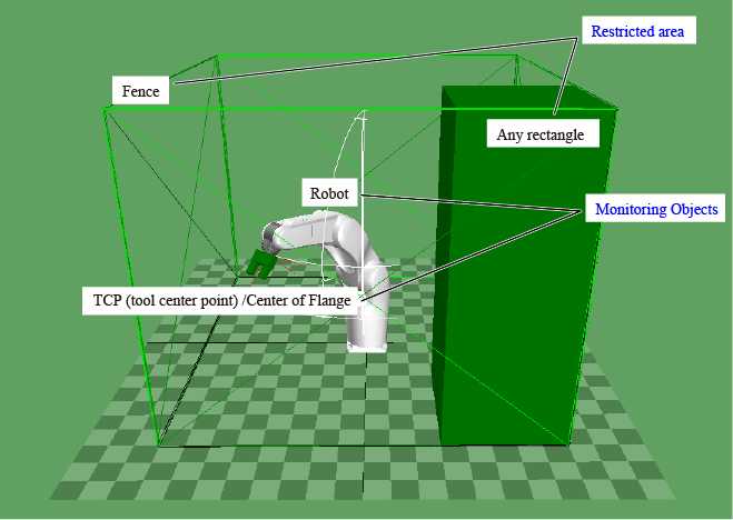
The following table briefly explains the types of monitoring target and restricted area.
| Category | Model name | Detail | |
|---|---|---|---|
| Monitoring target | Robot model | Monitors the robot speed and the outer diameter. Speed monitoring points are predetermined for each robot type. For details, refer to Points on the robot arm of Robot Speed Monitoring (RSM). |
|
| Tool model | Monitors the tool speed and the outer diameter. TCP and the center of flange are the speed monitoring points. To monitor whether if the tool is away from other devices, set the size of tool model equal to or larger than the outer diameter of the actual tool. |
||
| Restricted area | Permanently | Fence model | Monitoring target is always monitored whether if it is within the permanently restricted area. This restricted area must enclose the robot. |
| Temporary | Any rectangle model | Monitors the contact with the monitoring target. To monitor whether if the monitoring target is away from a certain peripheral device, set the size of rectangle model equal to or larger than the outer diameter of the peripheral device. This restricted area can be enabled/disabled by switching Monitoring area N disable input (N represents a number from 0 to 3). |
|
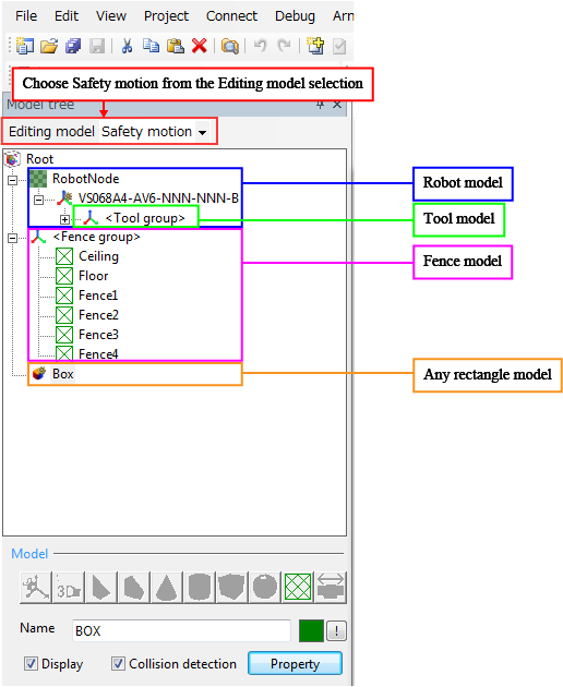
Modeling Method
To create a model, use WINCAPSIII. For details, please refer to Simple Modeling.
Restrictions for Creating Models
A model must be created in the specified layer.
| Model name | Restrictions |
|---|---|
| Robot model | must be located below the Root Node (except for Tool group). |
| Tool model | must be located below the Tool group. |
| Fence model | must be located immediate below the Root. |
| Any rectangle model | must be located immediate below the Root. |
ID : 2486