
ID : 3399
Setup Procedure when Operating with Three Robots and N Lines of Conveyor
Configure the shared conveyor setting for each of the master and slaves (two slave robots).
Hereafter, a robot controller which uses the dual arm control function is called a "dual arm controller", a robot controller which does not use the dual arm control function is called a "normal controller".
In this example, the setup target system has the following conditions.
- Set the Robot0 of the dual arm controller as a master
- Set the Robot1 of dual arm controller and the normal controller as slaves
- Connect the encoder to the 7th joint of the encoder hub
- Use the conveyor number 1
- Enter 192.168.0.1 for the IP address of dual arm controller, 192.168.0.2 for the IP address of normal controller
In actual setup, enter appropriate parameters according to the system you will setup.
The following describes the entire setup procedures.
| Process | Description |
|---|---|
|
To use an additional LAN board for communication between the master and slave (normal controller), you need to change the "Multicast. I/F [IP Address]" parameter from the default value. |
|
|
(Set with a Dual Arm Controller) |
|
|
(Set with a Dual Arm Controller) |
|
|
4. Slave (Normal Controller) Setting (Set with a Normal Controller) |
|
Because of the number of slaves and/or conveyors used, the CPU performance of the dual arm controller could be insufficient, leading to lower performance. In this case, reduce the number of slaves and/or conveyors and distribute the load to additional controller so that CPU load on the dual arm controller is reduced. Or, consider the use of a high-spec CPU installed robot controller.
1. Setting Procedure for Using an Additional LAN Board
To use an additional LAN board for communication between the master and slave (normal controller), you need to change the "Multicast. I/F [IP Address]" parameter from the default value. For details, refer to "Communication between Master and Slave by Using Additional LAN Board".
2. Master Setting (Set with a Dual Arm Controller)
1
Set the target robot of the teach pendant setting to Robot0.
Press the [Robot selection] button to display [Robot selection] window. From the [Robot selection] list, select [Robot0(R0)] and press the [OK] button.
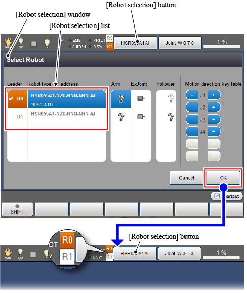
Check if an "R0" icon on the left of the [Robot selection] button turns orange. (See the above figure.)
2
Set an encoder-connected joint.
Set the user level to [Maintainer] and then follow the operation path below. [Motor Setting] window appears.
Operation path : [F2 Arm] - [F12 Maintenance] - [F10 Joint Settings] - [F6 Motor Setting] |
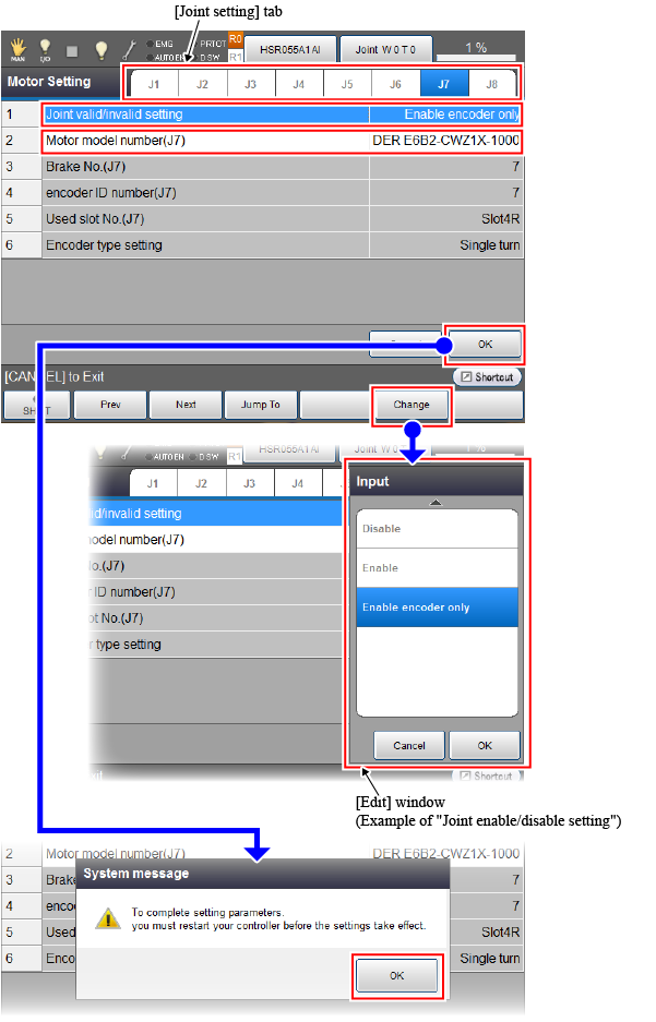
From the [Joint setting] tab, select a joint number.(For example, select "J7" for the 7th joint) When the motor setting parameter of the 7th joint is displayed, set each parameter as the following table shows.
|
Setting parameter (Number : Parameter name) |
Setting value |
|---|---|
| 1 : Joint enable/disable setting | Enable encoder only |
| 2 : Motor model number (J7) | ENCODER E6B2-CWZ1X-1000 |
Place the cursor on the parameter to set, and press [F5 Change]. Once the [Edit] window appears, select a value and then press [OK] button.
After all parameters have been set, press the [OK] button on the [Motor Setting] window. Once the system message of parameter setting completion appears, press [OK].
Before turning off the robot controller, check if the "Joint valid/invalid setting" of the 7th joint of Robot1 is set to "Disable". To check the setting, press the [Robot selection] button and set the teach pendant setting target robot to "Robot1". With referring to the above operation, display the [Motor Setting] window, check the motor setting of the 7th joint.
3
Reboot the robot controller
Turn off the robot controller and turn on the controller again.
Once the robot controller start up, set the teach pendant setting target robot to Robot0.
4
Set Robot0 as a master.
Set the user level to [Maintainer] and then follow the operation path below. [Tracking] window appears.
Operation path : [F10 Tracking] |
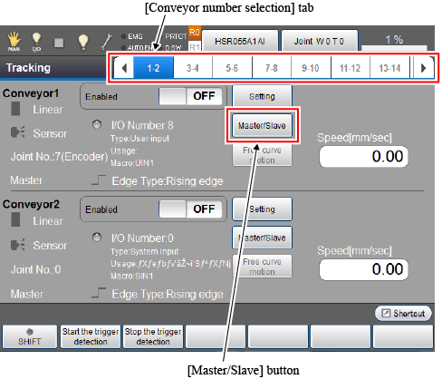
From the [Conveyor number selection] tab, select the [1-2] cell that indicates the conveyor number 1 and 2. Press the [Master/Slave] button of the conveyor number 1 to display the following [Master/Slave selection] window.
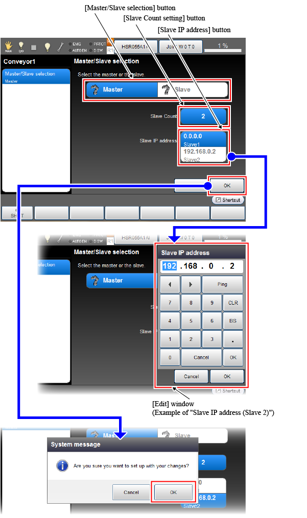
Set each parameter along with the following instructions.
| Items to set | Setting value / Setting method |
|---|---|
| Master/Slave selection |
Setting value : master |
|
How to set : Press [Master] of the [Master/Slave selection] button. ("Master" changes to blue.) |
|
| Slave Count |
Setting value : 2 |
|
How to set : Press the [Slave Count setting] button. On the [Edit] window, select "1". Press the [OK] button on the [Edit] window. |
|
| Slave IP address |
Setting value :
Slave1 is for Robot1, Slave2 is for the normal controller. Entering 0.0.0.0 will specify the other robot in the dual arm control function. In this example, Robot0 is set as a master. Therefore, "the other robot" means Robot1. Entering 0.0.0.0 means that Robot1 is specified. |
|
How to set : On the [Slave IP address setting] area, press Slave1 or Slave2. On the [Edit] window, enter the IP address and press the [OK] button. |
After all setting items have been set, press the [OK] button on the [Master/Slave selection] window. Once the following system message appears, press [OK] to back to the [Tracking] window.
If you change the conveyor's state from Slave to Master, when you press the [OK] button on the [Master·Slave Selection] window, two system messages are displayed in sequence. For each system message, press [OK] to back to the [Tracking] window.
5
Execute the hardware setting for conveyor, connection confirmation, and conveyor-robot(Robot0) calibration.
The operation procedure is the same as that of only one robot-used system. Refer to "Selecting a Hardware", "Hardware Connection Confirmation", "Calibration". However, be sure to keep the setting target robot of teach pendant as Robot0.
6
To use several conveyors, repeat the operation from STEP1 to STEP5 up to the number of conveyors.
3. Slave (Robot1) Setting (Set with a Dual Arm Controller)
1
Set the target robot of the teach pendant setting to Robot1.
Press the [Robot selection] button to change the target robot. (Refer to "STEP1" on "2. Master setting")
Check if an [R1] icon on the left of the [Robot selection] button turns orange. (See the figure below.)

2
Set Robot1 as a slave.
Set the user level to [Maintainer] and then follow the operation path below. [Tracking] window appears.
Operation path : [F10 Tracking] |
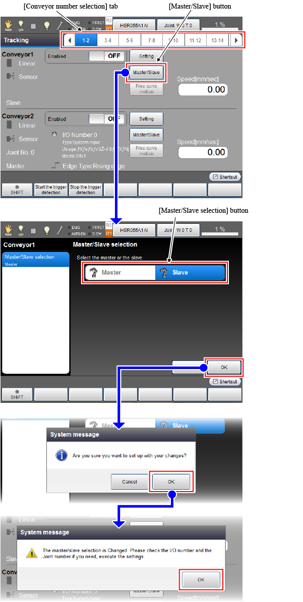
From the [Conveyor number selection] tab, select the [1-2] cell that indicates the conveyor number 1 and 2. Press the [Master/Slave] button of the conveyor number 1.
How to set: On the [Master/Slave selection] window, press [Slave] of the [Master/Slave selection] button. ("Slave" changes to blue.)
Pressing the [OK] button on the [Master/Slave selection] window displays the system message. Once the system message appears, press the [OK] button. Once the following system message appears, press [OK] to back to the [Tracking] window.
3
Execute the connection check with Master.
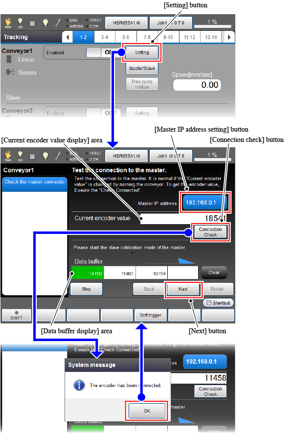
On the [Tracking] window, press the [Setting] button of the conveyor number 1.

A window to check the connection with master is displayed.
The following items are set in this window.
| Item / Process | What to do |
|---|---|
| 1. Master IP address setting |
Setting value : 0.0.0.0 (Entering 0.0.0.0 will specify a master robot. In this example, if 0.0.0.0 is entered, Robot0 will be specified.) |
|
How to set : Press the [Master IP address setting] button. On the [Edit] window, enter "0.0.0.0". Press the [OK] button on the [Edit] window. |
|
| 2. Connection check with Master |
Press the [Connection check] button to check that the system message for the encoder connection confirmation appears. Once the system message appears, press [OK] to back to the window for checking the connection with master. |
| 3. Encoder value acquisition check |
Run the setting target conveyor. (In this case, a conveyor which conveyor number is 1.) Whenever a trigger signal is input, encoder values are displayed in the [Data buffer display] area, starting from the left most cell. It is determined as normal if the encoder value of each cell displayed in the [Data buffer display] area are different. Check if the encoder value in the [Current encoder value] area is updated in real-time. |
When all items in the above table are set, press the [Next] button. On the left of the window, the [Conveyor figure selection] button is displayed.
4
Pressing the [Conveyor figure selection] button will display the setting window that offers the hardware setting (conveyor and device selection) used in the conveyor and the conveyor-robot (Robot1) calibration.
The operation procedure is the same as that of only one robot-used system. Refer to "Selecting the Conveyors and Devices" and "Calibration". However, be sure to keep the setting target robot of teach pendant as Robot1.
The following operations are not executed for the slave because these are not required.
- Encoder joint number setting
- I/O Setting
- Hardware Connection Confirmation
5
To use several conveyors, repeat the operation from STEP1 to STEP4 up to the number of conveyors.
4. Slave (Normal Controller) Setting (Set with a Normal Controller)
1
Set a normal controller as a slave.
Set the user level to [Maintainer] and then follow the operation path below. [Tracking] window appears.
Operation path : [F10 Tracking] |

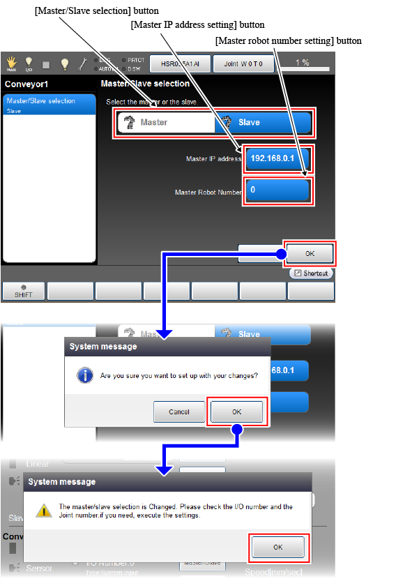
From the [Conveyor number selection] tab, select the [1-2] cell that indicates the conveyor number 1 and 2. Press the [Master/Slave] button of the conveyor number 1 to display the following [Master/Slave selection] window.
Set each parameter along with the following instructions.
| Items to set | Setting value / Setting method |
|---|---|
| Master/Slave selection |
Setting value : Slave |
|
How to set : Press [Slave] of the [Master/Slave selection] button. ("Slave" changes to blue.) |
|
| Master IP address |
Setting value : 192.168.0.1 |
|
How to set : Press the [Master IP address setting] button. On the [Edit] window, enter the IP address. Press the [OK] button on the [Edit] window. |
|
| Master robot number |
Setting value : 0 Specify which robot (Robot0 or Robot1) of the dual arm controller is a master. In this example, Robot0 is a master. Therefore, setting value is "0". ) |
|
How to set : Press the [Master robot number setting] button. On the [Edit] window, enter "0". Press the [OK] button on the [Edit] window. |
After all setting items have been set, press the [OK] button on the [Master/Slave selection] window. Once the system message appears, press [OK]. Once the following system message appears, press [OK] to back to the [Tracking] window.
2
Execute the connection check with Master.
On the [Tracking] window, press the [Setting] button of the conveyor number 1.
A window to check the connection with master is displayed.
The following items are set in this window.
| Item / Process | What to do |
|---|---|
| 1. Master IP address setting |
Setting value : 192.168.0.1 |
|
How to set : Press the [Master IP address setting] button. On the [Edit] window, enter "192.168.0.1". Press the [OK] button on the [Edit] window. |
|
| 2. Connection check with Master |
Press the [Connection check] button to check that the system message for the encoder connection confirmation appears. Once the system message appears, press [OK] to back to the window for checking the connection with master. |
| 3. Encoder value acquisition check |
Run the setting target conveyor. (In this case, a conveyor which conveyor number is 1.) Whenever a trigger signal is input, encoder values are displayed in the [Data buffer display] area, starting from the left most cell. It is determined as normal if the encoder value of each cell displayed in the [Data buffer display] area are different. Check if the encoder value in the [Current encoder value] area is updated in real-time. |
When all items in the above table are set, press the [Next] button. On the left of the window, the [Conveyor figure selection] button is displayed.
3
Pressing the [Conveyor figure selection] button will display the setting window that offers the hardware setting (conveyor and device selection) used in the conveyor and the conveyor-robot (robot of the normal controller) calibration.
The operation procedure is the same as that of only one robot-used system. Refer to "Selecting the Conveyors and Devices" and "Calibration".
The following operations are not executed for the slave because these are not required.
- Encoder joint number setting
- I/O Setting
- Hardware Connection Confirmation
4
To use several conveyors, repeat the operation from STEP1 to STEP3 up to the number of conveyors.
ID : 3399