
ID : 4887
Knowledge Required for Selection of Servomotors
This section describes basic knowledge required for selecting an optimal servomotor output and reduction gear ratio in designing of servo mechanism drive including robots.
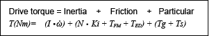
(1) Calculation of load drive torque (T ) (conversion into the motor shaft's)
| Symbol | Meaning | Unit |
|---|---|---|
| Total inertia moment in conversion into the motor shaft's | (Nms²) | |
| Motor shaft angle acceleration | (rad/s²) | |
| Motor usage rpm | (rpm) | |
| Braking constant (see motor catalog) | (Nm/rpm) | |
| Motor static friction torque (see motor catalog) | (Nm) | |
| Friction torque of transmission system, etc. (conversion into the motor shaft's) |
(Nm) | |
| Gravity holding torque (conversion into the motor shaft's) | (Nm) | |
| Interference torque, centrifugal force, coriolis force, etc. (conversion into the motor shaft's) |
(Nm) |
(2) Calculation of motor max. occurrence torque (TM) (conversion into the motor shaft's)
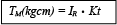
Where,
| Symbol | Meaning | Unit |
|---|---|---|
| Max. current value which can be applied to motor | (Ao·p) | |
| Torque constant (See motor catalog) | (Nm/Ao·p) |
Or this is shown by the "Instantaneous max. torque" in the motor catalog.
However, drive torque "T" shall be designed within 2.5 times of motor rated torque as MC8.
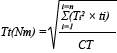
(3) Calculation and evaluation of effective torque
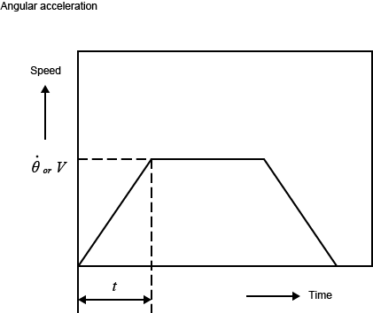
When the servomotor moves like figure below pattern, the effective torque (Tt ) of 1 cycle is achieved by the following equation.
However,
| Symbol | Meaning | Unit |
|---|---|---|
| Drive torque (T in equation (1)) | (Nm) | |
| Deceleration torque (subtract friction torque from T in equation (1)) | (Nm) | |
| Friction torque + particular torque | (Nm) | |
| Time of |
(sec) | |
| Cycle time | (sec) |
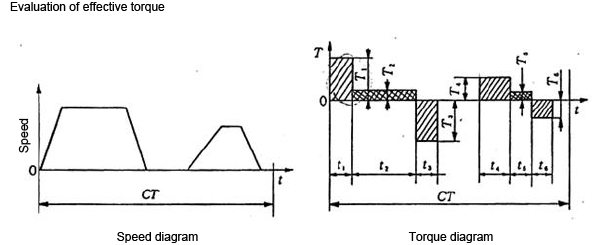 |
Evaluation of motor unit
Tt < TR (Rated torque in the motor catalog) shall be formed.
Use the motor within 80% of motor rated torque because of encoder circuit thermal limit (70℃).
When the effective torque is 80% or more of motor rated torque, measure the temperature of encoder circuit to check it is within the limit.
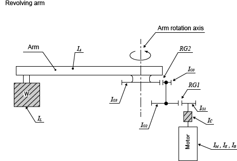
(4) Calculation of total inertia moment (I ) (conversion into the motor shaft's)
Revolving arm (Figure below)
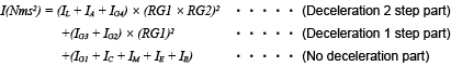
| Symbol | Meaning | Unit |
|---|---|---|
| Inertia moment of load W arm revolution shaft | (Nms²) | |
| Inertia moment of arm revolution shaft | (Nms²) | |
| 1st step pinion inertia moment | (Nms²) | |
| 1st step gear inertia moment | (Nms²) | |
| 2nd step pinion inertia moment | (Nms²) | |
| 2nd step gear inertia moment | (Nms²) | |
| Coupling inertia moment | (Nms²) | |
| Motor armature inertia moment | (Nms²) | |
| Encoder inertia moment | (Nms²) | |
| Built-in brake inertia moment | (Nms²) | |
| First step gear ratio | (1/n) | |
| Second step gear ratio | (1/n) |
 |
Linear movement arm(Figure below)
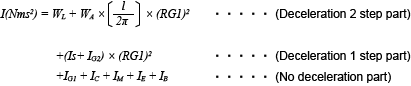
| Symbol | Meaning | Unit |
|---|---|---|
| Load weight | (kg) | |
| Arm weight | (kg) | |
| Inertia moment of ball screw | (Nms²) | |
| Lead of ball screw | (m/rev.) |
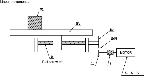 |
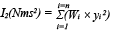
Calculation of rotor inertia moment (I1) (Figure below)
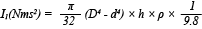
| Symbol | Meaning | Unit |
|---|---|---|
| Outer diameter | (m) | |
| Inner diameter | (m) | |
| Thickness | (m) | |
| Specific gravity | (kg/m³) |
When inertia is expressed by GD², divide it by 4×g.
Rotor
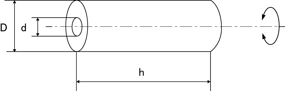
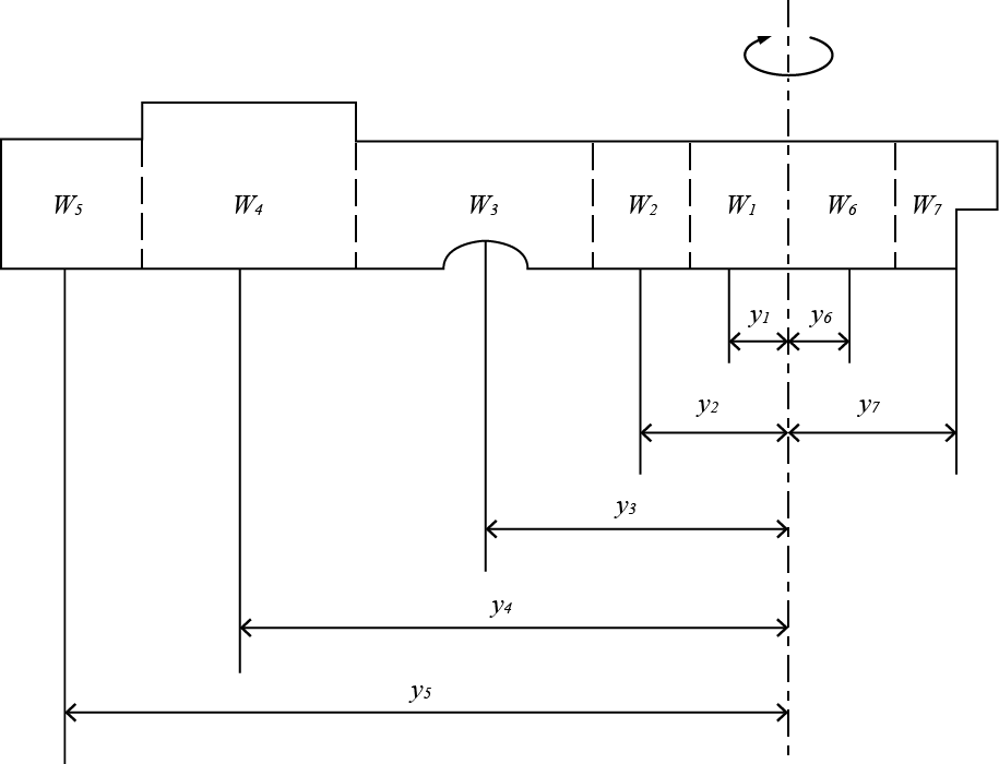
Calculation of complex shape unit inertia moment (I2) (Figure below)
Inertia moment of complex shape unit can not be achieved by the equation. Therefore, divide the unit into parts and achieve the inertia moment by each part and add such moments.
| Symbol | Meaning | Unit |
|---|---|---|
| Divided part weight | (kg) | |
| Distance from center of revolution to center of divided part | (m) |
Complex shape unit
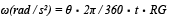
(5) Calculation of motor shaft angular acceleration (ω)
Revolving arm
Linear movement
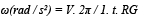
| Symbol | Meaning | Unit |
|---|---|---|
| Acceleration time | (sec) | |
| Arm revolving speed | (°/s) | |
| Linear speed | (m/s) | |
| Total deceleration ratio | (1/n) | |
| Ball screw, Rack & Pinion ··· Lead | (m/rev.) |
 |
(6) Friction torque of transmission system, etc. (TFD)
Divide the friction torque of the slide part, seal, speed reducer, etc. by deceleration ratio to make the quotient as the friction torque in conversion into the motor shaft.
Especially be sure to know that the transmission mechanism friction torque before deceleration is directly applied to the motor.
(7) Gravity holding torque (Tg)
When the gravity needs to be held, divide the holding unit weight by gear ratio to make the quotient as the gravity torque in conversion into the motor shaft's.
When taking gravity balance by air cylinder or counter weight, the gravity holding torque is "0". Be sure to check, however, the slide resistance of air cylinder and the addition of inertia moment.
(8) Particular load torque (Ts)
When the degree of freedom is "2" or more, sometimes interference torque or centrifugal force or corioli's force is applied by other shaft movement.
Achieve the sum of these forces by mechanism construction or motion speed and divide it by gear ratio to make the quotient as the torque in conversion into the motor shaft's.
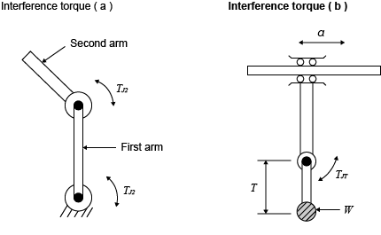
Particular load torque
- On two joint arm, second arm drive torque (TJ2) is applied to first arm. (see figure below :Interference torque (a))
- Also in combination of linear movement and revolving shaft movement, acceleration (α) of linear shaft is applied to the offset load (W) of the revolving shaft and torque (Tr) of the revolving shaft which is in proportion to the offset distance (r) occurs. (see figure below :Interference torque (b))

 |
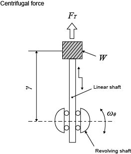
Example of centrifugal force (FT)
On an object (W) on the revolving shaft, centrifugal force (FT) occurs from center to outside in proportion to the square of revolving shaft angular speed (ωθ) and the revolving radius (r).

* On figure below, linear shaft supports centrifugal force.
 |
Example of Corioli's force (Fc)
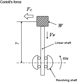
When an object (W) on the revolving shaft moves at VW speed, corioli's force (Fc) which is in proportion to the double of the product of W, revolving shaft angular speed (ωθ) and speed VW occurs in the vertical direction to VW on the object (W).
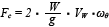
On Figure below, a torque which is the multiplication of corioli's force (Fc) by radius (r) occurs on the revolving shaft, and a friction resistance which is the multiplication of corioli's force (Fc) by slide part friction coefficient occurs on the linear shaft.
 |
ID : 4887